Self-contained water-mixing coupling pressure-bearing efficient energy-saving furnace body

A high-efficiency, energy-saving, water-mixing technology, applied in water heaters, fluid heaters, household heating, etc., can solve problems such as poor circulation of the loop, failure to achieve the expected effect, damage to the boiler circulation pump, etc., to avoid heating Inertial temperature rise, quantity expansion, and the effect of improving operating efficiency

Pending Publication Date: 2019-09-03
中山市曼卡热能科技有限公司
View PDF6 Cites 0 Cited by
  • Summary
  • Abstract
  • Description
  • Claims
  • Application Information

AI Technical Summary

Problems solved by technology

This is because the circulating pump power of the boiler itself is small, and the head is also relatively small. When the heating area is small, it can drive the hot water in the system to circulate better. But when the heating area is large, due to the large amount of circulating water in the system, the water resistance Larger so that some of the more distant circuits do not circulate well, resulting in poor localized heating
In order to solve this problem, some engineers tried to add a larger power circulating pump outside the main pipe of the water separator of the system to increase the hot water circulation pressure to improve the heating effect. Sometimes this can improve some problems, but often cannot meet expectations effect, and did not fundamentally solve the problem. The reason is that the additional circulating pump and the circulating pump of the wall-hung boiler will interfere with each other when they work at the same time, that is, coupling will occur, which will increase the energy consumption of the system and cannot solve the problem. May damage the boiler's own circulation pump

Method used


Image

  • Self-contained water-mixing coupling pressure-bearing efficient energy-saving furnace body
  • Self-contained water-mixing coupling pressure-bearing efficient energy-saving furnace body

Examples


Embodiment Construction

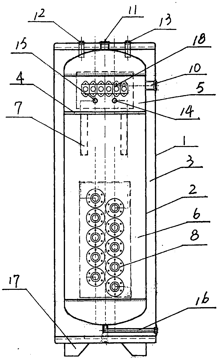
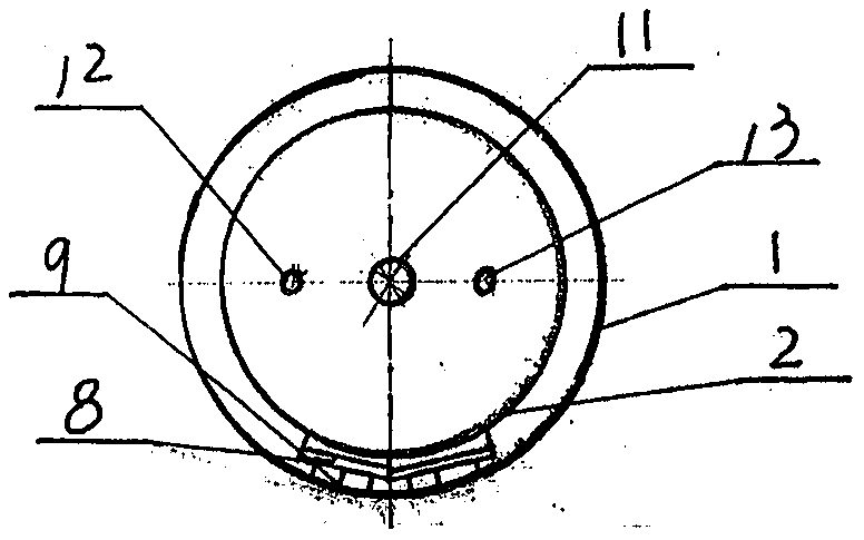
[0013] Such as figure 1 , figure 2 As shown, a stainless steel liner 2 with its own mixed-water coupling, pressure-bearing, high-efficiency and energy-saving furnace body is set in the shell 1, the insulation layer 3 is set in the middle of the shell 1 and the stainless steel liner 2, and the heating body 8 is fixedly arranged in the stainless steel liner 2. The front lower end of the heating chamber 6 in the lower part extends into the heating chamber 6 in parallel. The isolation plate 4 is arranged on the upper middle part of the stainless steel liner 2. The upper part of the isolation plate 4 is the mixing water coupling chamber 5, and the lower part is the heating chamber 6. Two The water-mixing coupling pipe 7 is equidistantly arranged at the lower end of the isolation plate 4 and connects the water-mixing coupling chamber 5 and the heating chamber 6. The return pipe 10 is arranged in the right middle part of the water-mixing coupling chamber 5, and the outlet pipe 11 is...


PUM


Abstract

The invention discloses a self-contained water-mixing coupling pressure-bearing efficient energy-saving furnace body. A stainless steel inner container (2) of the self-contained water-mixing couplingpressure-bearing efficient energy-saving furnace body is arranged in a shell (1) through a heat preservation layer (3), a heating body (8) is fixedly arranged at the front lower end of a heating bin (6) at the lower part of the stainless steel inner container (2), an isolation plate (4) is arranged in the upper middle part of the stainless steel inner container (2), the upper part of the isolationplate (4) is a water-mixing coupling bin (5), the lower part is the heating bin (6), and two water-mixing coupling pipes are arranged at the lower end the isolation plate (4) at equal intervals and enable the water-mixing coupling bin (5) and the heating bin (6) communicates with each other. Due to the fact that a water-mixing system is scientifically designed, the outflow water temperature is stable, and energy conservation and consumption reduction are achieved, the water capacity is increased, the heating is conducted during the valley electricity price, the heat dissipation is conducted during the peak electricity price, so that the energy is saved and the consumption is reduced, and the cost is saved; and a heating body adopts a nickel complex alloy high-temperature heating wire andadopts a underneath type, the thermal load of the surface is reduced, the thermal efficiency is greatly improved, the working performance is stable, and the service life is prolonged.

Description

[0001] Technical field: [0002] The invention relates to a high-efficiency and energy-saving furnace body with its own mixing water coupling, pressure bearing, and widely used in various occasions for water storage heating. [0003] Background technique: [0004] The electric hot water boilers currently used in the market, in the actual use of heating, generally exist that the power design of the boiler is sufficient, the heat load design is no problem, and the system design is no problem, but some local rooms are not hot, and these phenomena It is mainly reflected in houses with larger areas or split-level duplexes. This is because the power of the circulation pump of the boiler itself is small, and the head is also relatively small. When the heating area is small, it can drive the hot water in the system to circulate better. Larger, so that some of the more distant circuits do not circulate well, resulting in poor local heating. In order to solve this problem, some enginee...

Claims


Application Information

Patent Timeline
Patent Type & Authority Applications(China)
IPC IPC(8): F24H1/20F24H9/18F24H9/20F24H9/00F24D13/04
CPCF24H1/201F24H9/1818F24H9/2014F24H9/0005F24D13/04
Inventor 曹尚生
Owner 中山市曼卡热能科技有限公司
Why Eureka
Try Eureka