
A concrete 3D printing U-shaped nail automatic nailing system

A 3D printing and concrete technology, applied in the field of 3D printing, can solve the problems that 3D printing concrete is difficult to meet the load-bearing requirements of the project, there is no vertical printing interlayer reinforcement equipment, and the mechanical properties of 3D printing components are weakened, so as to ensure continuous and uninterrupted Sexuality, high degree of automation, to achieve the effect of control

Active Publication Date: 2020-05-26
HEBEI UNIV OF TECH
View PDF1 Cites 0 Cited by
  • Summary
  • Abstract
  • Description
  • Claims
  • Application Information

AI Technical Summary

Problems solved by technology

[0003] However, the process of 3D printing stacking layer by layer is difficult to bind the reinforcement cage like the traditional formwork pouring method
Without the implantation of steel bars, the structure of 3D printed concrete will be difficult to meet the actual load-bearing requirements of the project
3D printed concrete has a certain weak interface between the printed layers due to the water content on the surface of the extruded material, which greatly weakens the mechanical properties of the 3D printed components.
The document with application number 201810616915.3 discloses an interlayer reinforcement technology for 3D printing of fiber-reinforced composite materials, but this device is suitable for the toughening of 3D printed concrete in the horizontal direction, and cannot solve the toughening problem of vertical delamination
At present, there is no research on vertical printing interlayer reinforcement equipment

Method used


Image

  • A concrete 3D printing U-shaped nail automatic nailing system
  • A concrete 3D printing U-shaped nail automatic nailing system
  • A concrete 3D printing U-shaped nail automatic nailing system

Examples


Embodiment Construction

[0030] Specific examples of the present invention are given below. The specific embodiments are only used to further describe the present invention in detail, and do not limit the protection scope of the claims of the present application.

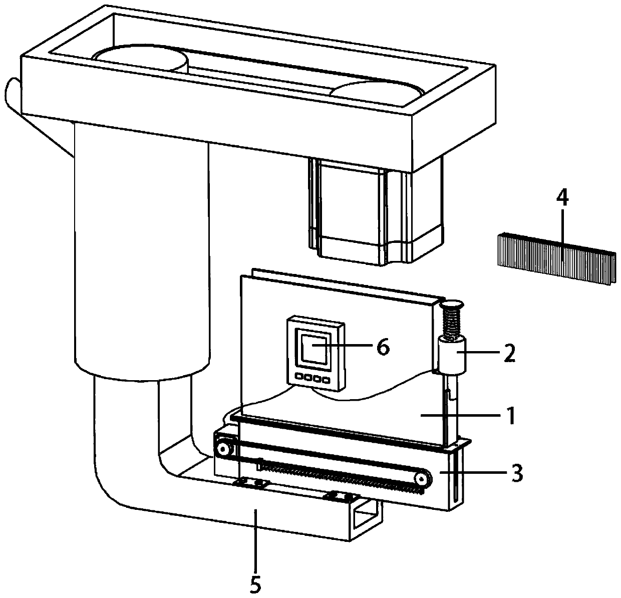
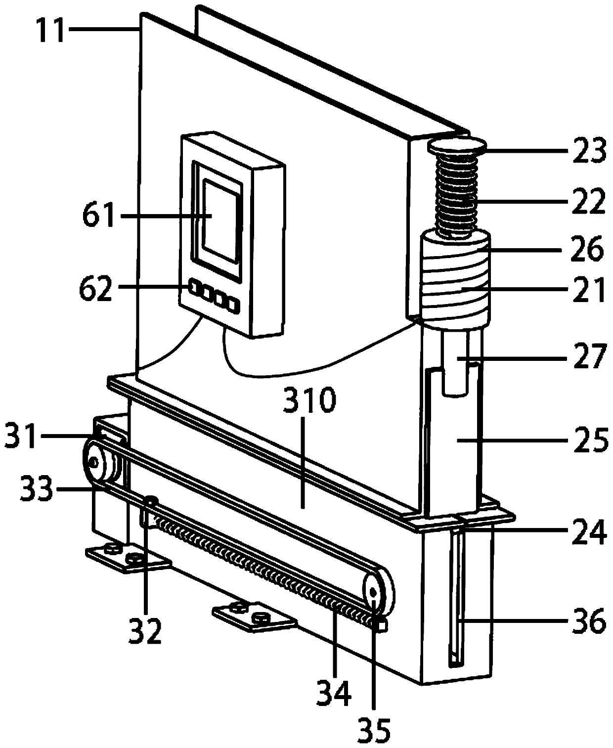
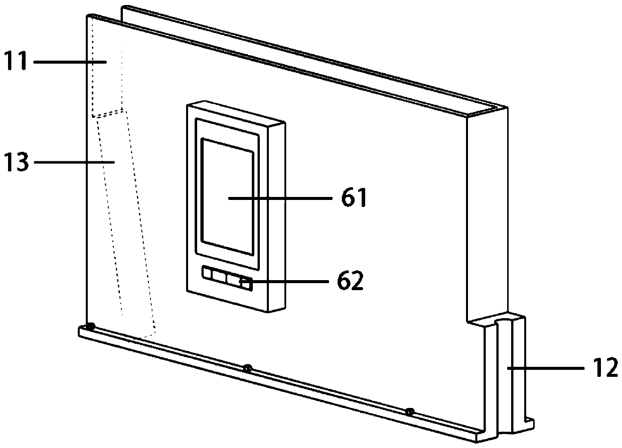
[0031] The present invention provides a concrete 3D printing U-shaped nail automatic placement system (referred to as the nail placement system), which is characterized in that the nail placement system includes a nail storage box 1, a striker mechanism 2, a U-shaped nail transmission mechanism 3 and an electronic control system 6. The striker mechanism 2 includes an electromagnet excitation device 21, a return spring 22, a limiter 23, a striker slider 24 and a striker 25; the staple delivery mechanism 3 includes a conveyor belt motor 31, a conveyor belt 33, and a conveyor spring 34 , conveyor belt runner 35, striker slider track 36, nail outlet 37, nail delivery slider track 38, nail delivery slider 39 and housing 310;

[0032] The bottom...


PUM


Abstract

The invention discloses an automatic U-shaped nail distributing system for concrete 3D printing. The automatic U-shaped nail distributing system comprises a nail storage box, a striking pin mechanismand a U-shaped nail conveying mechanism, wherein the striking pin mechanism comprises an electromagnet excitation device, a reset spring, a limiter, a striking pin sliding block and a striking pin; and the U-shaped nail conveying mechanism comprises a conveyor belt motor, a conveyor belt, a conveying spring, a conveyor belt rotating wheel, a striking pin sliding block rail, a nail discharging opening, a nail feeding sliding block rail, a nail feeding sliding block and a shell. According to the nail distributing system, the vertical interlayer reinforcement of 3D printing concrete members can be realized, the problem that a weak interface exists between the 3D printing layers is solved, the mechanical property is improved, the 3D printing concrete interlayer shear is strengthened and toughened, and the toughness and the strength of the 3D printing members are improved; the U-shaped nails are adaptively arranged along a 3D printing path; and the U-shaped nails can be added at any time inthe 3D printing process, and the continuity of placing the U-shaped nails in the printing process is guaranteed through cooperative control of the conveyor belt and the striking pin mechanism.

Description

technical field [0001] The invention belongs to the field of 3D printing, in particular to an automatic nailing system for concrete 3D printing U-shaped nails. Background technique [0002] With the rapid development of my country's construction industry, traditional construction methods have gradually become unsuitable for modern construction projects due to their shortcomings such as high energy consumption, high pollution, and low efficiency. 3D printing technology, as a new technology for intelligent construction, has become a solution An important method for traditional construction problems, using automated facilities, can realize engineering construction quickly, flexibly and environmentally friendly. 3D printing technology is also gradually being applied in the construction industry. 3D printing concrete technology is a process of extruding cement-based building materials through nozzles through automated equipment such as robotic arms, and performing additive manufa...

Claims


Application Information

Patent Timeline
Patent Type & Authority Patents(China)
IPC IPC(8): B28B1/00B33Y30/00
CPCB28B1/001B33Y40/00
Inventor 王里马国伟
Owner HEBEI UNIV OF TECH
Learn More