Underground diaphragm wall and construction method thereof

An underground continuous wall and connecting plate technology, applied in artificial islands, sheet pile walls, water conservancy projects, etc., can solve the problems of low anti-seepage performance, low structural strength and high engineering cost at joints, and ensure structural strength and anti-seepage. performance, improved strength and impermeability, the effect of high surface flatness

Pending Publication Date: 2019-08-30
THE FIRST COMPARY OF CHINA EIGHTH ENG BUREAU LTD
View PDF0 Cites 0 Cited by
  • Summary
  • Abstract
  • Description
  • Claims
  • Application Information

AI Technical Summary

Problems solved by technology

If the pull-out time is too early, the strength of the poured underground diaphragm wall will be insufficient, which will lead to quality accidents; if the pull-out time is too late, it will be difficult to pull out because the joint pipe or joint box is bonded to the concrete
In addition, because there is generally mud in the groove section, if the construction time of the lower underground diaphragm wall is long, a layer of mud skin will be attached to the joint of the poured underground diaphragm wall, which will lead to the strength of the connection between the joint and the diaphragm wall. Low anti-seepage performance
When I-steel joints are used, the I-steel web is prone to mud inclusions, resulting in low anti-seepage performance at the joints
In addition, since the existing underground diaphragm wall is cast in-situ in the groove section, its structural strength is low and its anti-seepage performance is poor
[0003] In summary, the existing underground diaphragm walls have the problems of low structural strength and poor anti-seepage performance, which not only affects the quality of subsequent projects, but also makes it difficult for underground diaphragm walls to meet the requirements of being used as permanent support structures. Therefore, underground diaphragm walls are generally only Can be used as a temporary support
Due to the complex construction process and high engineering cost of the underground diaphragm wall, it causes a lot of waste as a temporary support structure

Method used


Image

  • Underground diaphragm wall and construction method thereof
  • Underground diaphragm wall and construction method thereof
  • Underground diaphragm wall and construction method thereof

Examples


Embodiment Construction

[0035] In order to clearly illustrate the technical features of the solution, the solution will be described below through specific implementation modes.

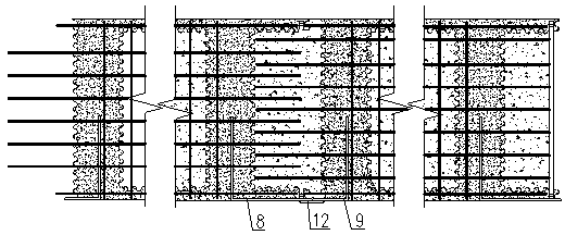
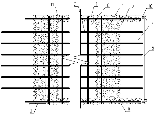
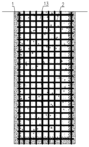
[0036] see Figure 1 to Figure 3 , the embodiment of the present invention provides an underground continuous wall, which includes several prefabricated wall units connected end to end in sequence, connecting plates 12 arranged between the outer sides of adjacent prefabricated wall units, and arranged on In-situ concrete 13 inside each prefabricated wall unit and between adjacent prefabricated wall units.

[0037] Further, the prefabricated wall unit includes a prefabricated concrete component 4, and a reinforcement cage 2 integrated with the prefabricated concrete component 4, which is fixedly connected with the reinforcement cage 2 respectively, is poured at both ends of the prefabricated concrete component 4 correspondingly, and is connected with the prefabricated concrete component 4 respectively. The first water-stop ...


PUM


Abstract

The invention discloses an underground diaphragm wall and a construction method thereof, and belongs to the technical field of building construction. According to the technical scheme, the undergrounddiaphragm wall comprises a plurality of prefabricated wall units which are sequentially connected end to end, connecting plates arranged between the outer side surfaces of the adjacent prefabricatedwall units, and cast-in-place concrete arranged inside each prefabricated wall unit and between the adjacent prefabricated wall units. The underground diaphragm wall has the beneficial effects that the underground diaphragm wall can be used as a permanent structure, waste is reduced, and the construction method of the underground diaphragm wall is low in cost, high in construction efficiency and high in pouring quality.

Description

technical field [0001] The invention relates to the technical field of building construction, in particular to an underground continuous wall and a construction method thereof. Background technique [0002] With the large-scale subway construction in my country's cities, underground diaphragm walls are widely used in subway construction. The underground diaphragm wall is constructed by segmental pouring, that is, a section of the underground diaphragm wall is dug first, and then the steel cage is lowered and concrete is poured. After the underground diaphragm wall reaches a certain strength, the construction of the next underground diaphragm wall is carried out. In order to meet the construction method and ensure the connection requirements of two adjacent underground diaphragm walls, it is necessary to install underground diaphragm wall joints at the junction of two adjacent underground diaphragm walls. At present, the form of underground diaphragm wall joints is mainly thr...

Claims


Application Information

Patent Timeline
Patent Type & Authority Applications(China)
IPC IPC(8): E02D5/20E02D29/16E02D31/02
CPCE02D5/20E02D29/16E02D31/02E02D2300/002E02D2300/0029
Inventor 刘先观鲁凯亓祥成王晓宾邢朝伟许利彤王闵闵杨守兴张宝峰李应心王超伟
Owner THE FIRST COMPARY OF CHINA EIGHTH ENG BUREAU LTD
Why Eureka
Try Eureka