A kind of incinerator automatic slag removal device for preparing 3-aminopropanol

A technology of automatic slag removal and aminopropanol, applied in the direction of incinerator, combustion type, combustion method, etc., can solve the problems of unsanitary, high cost, difficult to manufacture, etc., and achieve the effect of easy cleaning

Active Publication Date: 2020-07-03
安庆市鑫富化工有限责任公司
View PDF6 Cites 0 Cited by
  • Summary
  • Abstract
  • Description
  • Claims
  • Application Information

AI Technical Summary

Problems solved by technology

[0002] Chemical waste is the leftovers left over from the production and utilization of chemical raw materials, or the waste that is polluted and cannot be reused during the production process. Chemical waste is often treated in an incinerator, using high-temperature heat treatment technology, with a certain amount of excess air Oxidative combustion reaction with the processed chemical waste in the incinerator. The harmful and toxic substances in the waste are oxidized and pyrolyzed at high temperature and destroyed. The waste will produce waste residue after being incinerated by the incinerator. Some large incinerators have automatic The slag removal system can realize automatic slag removal, but the structure of the automatic slag removal system is complex, difficult to manufacture and high in cost, while small and medium-sized incinerators can only use manual slag removal, which is unhygienic and wastes manpower and material resources. The boiler structure needs to be improved

Method used


Image

  • A kind of incinerator automatic slag removal device for preparing 3-aminopropanol
  • A kind of incinerator automatic slag removal device for preparing 3-aminopropanol
  • A kind of incinerator automatic slag removal device for preparing 3-aminopropanol

Examples


Embodiment 1

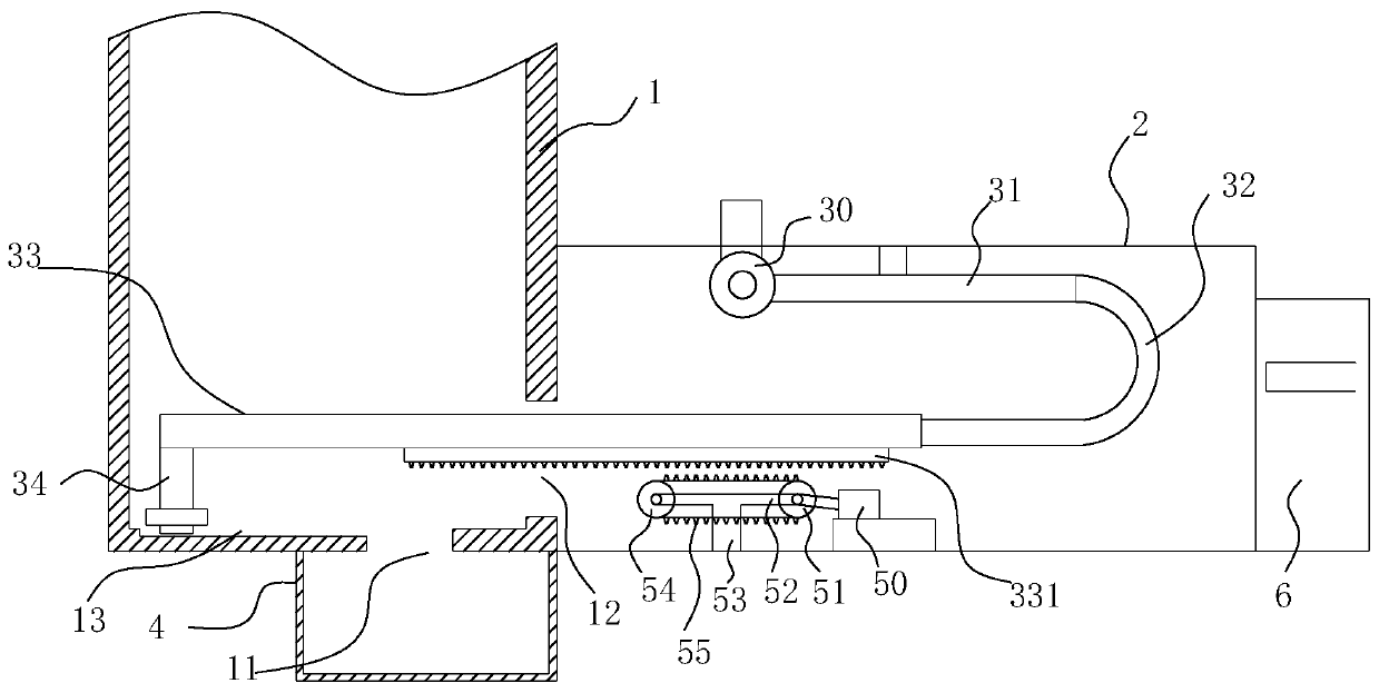
[0023] Such as figure 1 , figure 2 Shown, a kind of incinerator automatic deslagging device for preparing 3-aminopropanol comprises:

[0024] An incinerator 1, the bottom of the incinerator 1 is provided with an ash outlet 11, and the right side wall of the incineration wheel 1 is provided with a through hole 12, and a box body 2 is provided outside the through hole 12;

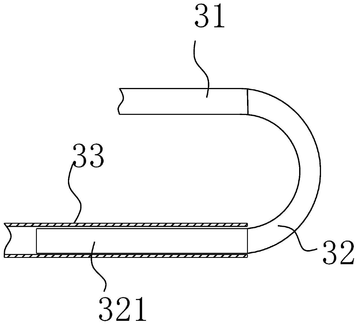
[0025] Such as image 3 , Figure 4 As shown, the slag removal mechanism is arranged in the box body 2, wherein the slag removal mechanism includes a driving device arranged at the bottom of the box body 2, a moving tube 33, and the left end of the moving tube 33 passes through the through hole 12 and extends to In the incinerator 1, a longitudinal pipe 34 is arranged at the left end of the moving pipe 33, a dust scraper 35 is arranged at the bottom of the longitudinal pipe 34, a rack 331 is arranged on the bottom wall of the moving pipe 33, and a fixed pipe is movable inside the right end of the moving p...

Embodiment 2

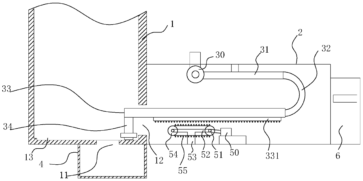
[0032] Such as figure 1 , figure 2 Shown, a kind of incinerator automatic deslagging device for preparing 3-aminopropanol comprises:

[0033] An incinerator 1, the bottom of the incinerator 1 is provided with an ash outlet 11, and the right side wall of the incineration wheel 1 is provided with a through hole 12, and a box body 2 is provided outside the through hole 12;

[0034] Such as image 3 , Figure 4 As shown, the slag removal mechanism is arranged in the box body 2, wherein the slag removal mechanism includes a driving device arranged at the bottom of the box body 2, a moving tube 33, and the left end of the moving tube 33 passes through the through hole 12 and extends to In the incinerator 1, a longitudinal pipe 34 is arranged at the left end of the moving pipe 33, a dust scraper 35 is arranged at the bottom of the longitudinal pipe 34, a rack 331 is arranged on the bottom wall of the moving pipe 33, and a fixed pipe is movable inside the right end of the moving p...


PUM


Abstract

The invention discloses an incinerator automatic slag removal device used for preparing 3-aminopropanol. The incinerator automatic slag removal device comprises an incinerator and a slag removal mechanism. An ash outlet is arranged at the bottom of the incinerator, a through hole is formed in the right side wall of the incinerator, and a box is arranged outside the through hole. The slag removal mechanism is arranged in the box and comprises a drive device arranged at the bottom of the box and a moving pipe. The left end of the moving pipe penetrates through the through hole and extends into the incinerator, a longitudinal pipe is arranged at the end of the moving pipe, and an ash scraping plate is arranged at the bottom of the longitudinal pipe. A rack is arranged on the bottom wall of the moving pipe. A fixed pipe is movably arranged in the right end of the moving pipe, the right end of the fixed pipe is connected with a ventilation pipe at the top of the box through a U-shaped connecting pipe, and the ventilation pipe communicates with a cooling fan arranged outside the box. Automatic ash removal action to the bottom face of the incinerator is achieved.

Description

Technical field: [0001] The invention relates to the field of chemical production equipment, in particular to an automatic slag removal device for an incinerator used for preparing 3-aminopropanol. Background technique: [0002] Chemical waste is the leftovers left over from the production and utilization of chemical raw materials, or the waste that is polluted and cannot be reused during the production process. Chemical waste is often treated in an incinerator, using high-temperature heat treatment technology, with a certain amount of excess air It reacts with the processed chemical waste in the incinerator. The harmful and toxic substances in the waste are oxidized and pyrolyzed at high temperature and destroyed. After the waste is incinerated, it will produce waste residue. Some large incinerators have automatic The slag removal system can realize automatic slag removal, but the automatic slag removal system has a complex structure, is difficult to manufacture and has hig...

Claims


Application Information

Patent Timeline
Patent Type & Authority Patents(China)
IPC IPC(8): F23G5/44F23J1/06
CPCF23G5/44F23J1/06
Inventor 汪文彬陈良斌张新宇
Owner 安庆市鑫富化工有限责任公司
Why Eureka
Try Eureka