
Pipeline optical power cable laying power assisting device

A power-assisted device and photoelectric technology, applied in the direction of optical fiber/cable installation, cable laying equipment, etc., can solve the problem of inconvenient laying of optical cables or guide wires, etc., to achieve the effect of increasing stability and reducing difficulty

Active Publication Date: 2019-08-16
NANJING LONGMA COMM ENG CO LTD
View PDF8 Cites 3 Cited by
  • Summary
  • Abstract
  • Description
  • Claims
  • Application Information

AI Technical Summary

Problems solved by technology

[0005] Although the quality of this communication pipeline lead laying device is small, it is easy to carry and operate, and at the same time it is conducive to the flexible advancement and adjustment of the posture of the lead wire laying device in the underground pipeline, but in the actual use process, this communication pipeline lead laying device can only Walking in a straight line in the pipeline, it is inconvenient for people to change directions and lay optical cables or guide wires in the well.

Method used


Image

  • Pipeline optical power cable laying power assisting device
  • Pipeline optical power cable laying power assisting device
  • Pipeline optical power cable laying power assisting device

Examples


Embodiment

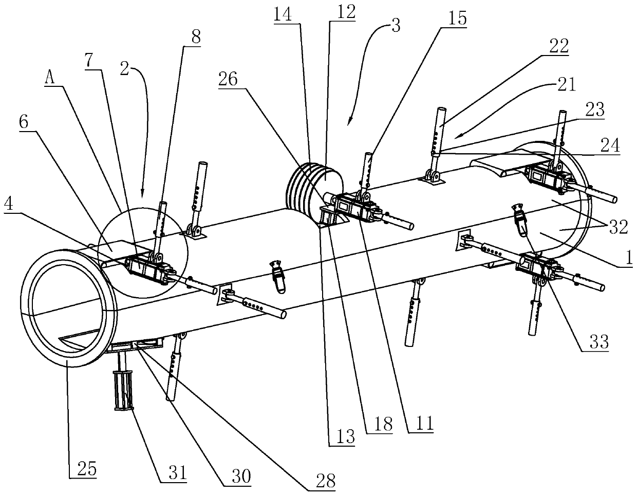
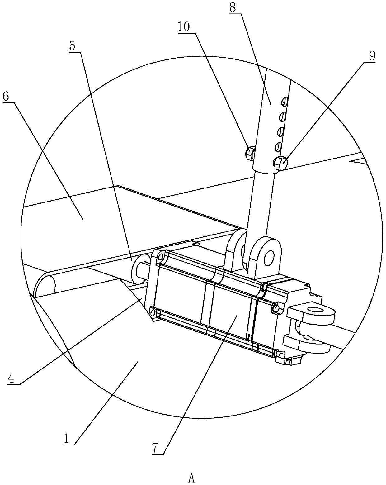
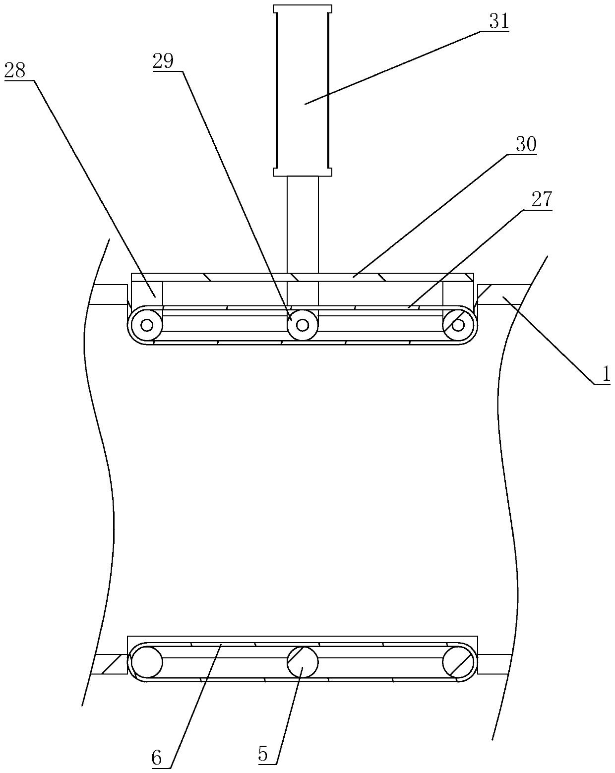
[0038] Embodiment: A kind of pipeline optical cable laying assistance device, refer to figure 1, including a multi-section flexible hose 1, the hose 1 is composed of two split parts 32. During installation, the operator splices the two split bodies 32 together correspondingly, and fixes the two split bodies 32 together through buckles 33 to form the hose 1 .

[0039] refer to figure 1 , The two ends of the hose 1 are welded with positioning rings 25 , and the positioning rings 25 are surrounded by two semicircular ring blocks on the outer periphery of the hose 1 . The setting of the positioning ring 25 plays a role of supporting and shaping the end of the hose 1 and enhances the stability of the overall structure of the hose 1 . The circumferential side of the hose 1 is provided with a telescopic support assembly 21. There are multiple sets of telescopic support assemblies 21 in the axial direction of the hose 1. The telescopic support assembly 21 includes a positioning supp...


PUM


Abstract

The invention discloses a pipeline optical power cable laying power assisting device and belongs to the technical field of communication equipment. The technical scheme is mainly characterized in thatthe device comprises multiple sections of flexible pipes, driving assemblies arranged on the flexible pipes and power assisting units arranged in the flexible pipes. The power assisting units are arranged in the axial direction and the turning points of the flexible pipes. The power assisting units and the flexible pipes are in detachable connection. Each driving assembly comprises a support frame arranged on the flexible pipe, a plurality of driving shafts in the support frame and a driving band wrapping the plurality of driving shafts. One driving shaft is provided with a driving motor; theouter side of the flexible pipe is provided with a driving motor; one driving shaft is coaxially connected with a rotating shaft of the driving motor; and the two groups of driving assemblies are symmetrical with respect to the center of the flexible pipe. The power assisting device has the technical effects of reducing operation difficulty in laying and turning of an optical power cable in the flexible pipes.

Description

technical field [0001] The invention relates to the field of communication technology equipment, in particular to an assisting device for laying a pipeline optical cable. Background technique [0002] At present, in communication engineering, the laying of optical cables is an important link in the construction of communication systems. The optical cables in the new tube holes are protected by hard plastic tubes. The existing Φ90mm standard cement tube holes can accommodate three 28 / 32mm plastic tube holes. Sub-pipe; Φ110mm standard plastic pipe can hold 4 sub-pipes of 28 / 32mm. The length of the plastic tube once deployed is based on the principle of facilitating the insertion of the optical cable. [0003] First, use a fiberglass pipe piercer to penetrate the pipe hole from one well to another well, bring in the lead wire, and lay out the plastic sub-pipe, then use the fiberglass pipe piercer to penetrate into the plastic sub-pipe hole and bring in the lead wire and optic...

Claims


Application Information

Patent Timeline
IPC IPC(8): H02G1/08G02B6/54
CPCG02B6/54H02G1/08
Inventor 张枫华张朱晨
Owner NANJING LONGMA COMM ENG CO LTD
Learn More