Self-powered photoelectric detection structure based on graphene-gallium oxide phase junction, device and preparation method

A photoelectric detection and gallium oxide technology, which is applied in the field of photoelectric detection, can solve the problems such as the reduction of photodetection rate, and achieve the effects of high sensitivity, easy large-scale production, and simple preparation process

Inactive Publication Date: 2019-08-02
唐为华
View PDF3 Cites 11 Cited by
  • Summary
  • Abstract
  • Description
  • Claims
  • Application Information

AI Technical Summary

Problems solved by technology

[0008] Aiming at the problems in this field, the present invention aims to solve the problem that the photodetection rate of the existing gallium oxide photodetector is reduced due to the use of opaque metal as the positive electrode

Method used


Image

  • Self-powered photoelectric detection structure based on graphene-gallium oxide phase junction, device and preparation method
  • Self-powered photoelectric detection structure based on graphene-gallium oxide phase junction, device and preparation method
  • Self-powered photoelectric detection structure based on graphene-gallium oxide phase junction, device and preparation method

Examples


Embodiment 1

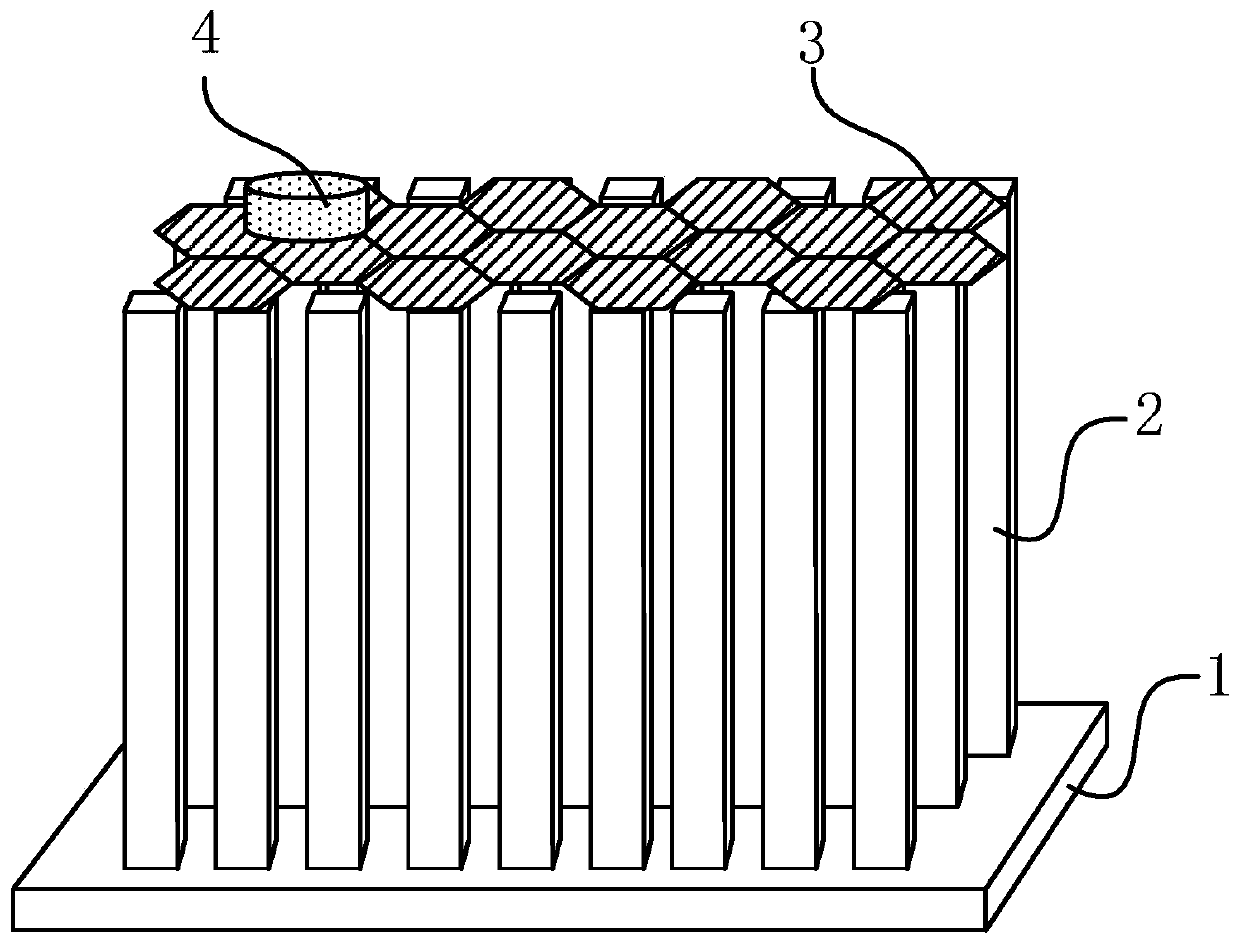
[0037] A graphene-α / β-Ga based 2 o 3 Phase-junction nanocolumn solar-blind ultraviolet detector, its preparation method is as follows:

[0038] (1) Pretreatment of the FTO conductive glass substrate: Ultrasonic cleaning with acetone, absolute ethanol, and deionized water for 10 min, and then drying in an oven.

[0039] (2) Preparation of α / β-Ga by hydrothermal method and annealing method 2 o 3 Nanopillar array: lean the FTO conductive glass against the inner wall of the stainless steel autoclave, add 5-10mL of 0.5g / 30mL Ga(NO 3 ) 3 The growth solution (covering 80% of the substrate), tightening the reaction vessel, and heating in an oven at 150° C. for 6 to 12 hours, can obtain GaOOH nanocolumn arrays grown along the (110) crystal plane. After the reaction was completed, the FTO substrate was taken out, rinsed with deionized water, and dried at 50°C. Then the gallium oxyhydroxide nanocolumn array was annealed at 500 °C for 4 hours to prepare α-Ga 2 o 3 array of nanopilla...

Embodiment 2

[0045] Steps (1), (2), (3) and (4) are all the same as in Example 1. After step (4) finishes, use the obtained graphene / nano-column / FTO sample to scoop up another piece of etching and clean it completely clean graphene. PMMA / bilayer graphene / α / β-Ga 2 o 3 After the nanocolumn / FTO sample was air-dried for 8 hours, put it on a constant temperature table to dry the sample completely, and then put it into a dichloromethane solution at 40°C to remove the PMMA glue; to obtain the sample double-layer graphene / α / β-Ga 2 o 3 Nanopillars / FTO.

[0046] The resulting bilayer graphene / α / β-Ga 2 o 3 The nanocolumn / FTO structure is similar to Example 1. Based on bilayer graphene / α / β-Ga 2 o 3 A voltage is applied across the electrodes of the nanocolumn / FTO sun-blind ultraviolet detector to measure the photoelectric performance. The I-t curve is measured at a voltage of 0 volts. It is found that the current changes instantaneously when the ultraviolet light switch is controlled, indicatin...


PUM

PropertyMeasurementUnit
thicknessaaaaaaaaaa
thicknessaaaaaaaaaa
electrical resistanceaaaaaaaaaa

Abstract

The invention discloses a self-powered photoelectric detection structure based on graphene-gallium oxide phase junction, a corresponding preparation method and a photoelectric detector. The structurecomprises a substrate, gallium oxide phase junction nano columns formed on the substrate and a graphene film formed on the gallium oxide phase junction nano columns. The method comprises the steps ofgenerating gallium oxide phase junction nano columns on the substrate through hydrothermal, annealing and high temperature annealing, and transferring and forming a graphene film on the gallium oxidephase junction nano columns. The structure has the advantages of simple preparation process, low cost, easy mass production and the like. The photoelectric detector has the characteristics of self-power supply and good spectral selectivity, and has the properties such as high responsiveness and high sensitivity to sunblind ultraviolet light.

Description

technical field [0001] The invention belongs to the technical field of photoelectric detection, and in particular relates to a self-powered photoelectric detection structure, device and preparation method based on a graphene-gallium oxide junction. The invention can be applied to solar-blind deep ultraviolet detectors. Background technique [0002] In recent years, silicon carbide, gallium nitride, aluminum nitride, zinc selenide, zinc oxide, gallium oxide and other bandgap E g The third-generation semiconductor material greater than 2.3eV, compared with the previous two generations of semiconductor materials, this type of material has a large band gap, high breakdown electric field strength, fast saturated electron drift speed, high thermal conductivity, small dielectric constant, and radiation resistance It has strong ability and good chemical stability, and is very suitable for the development of radiation-resistant, high-frequency, high-power and high-density integrated...

Claims


Application Information

Patent Timeline
Patent Type & Authority Applications(China)
IPC IPC(8): H01L31/0224H01L31/102H01L31/18
CPCH01L31/022408H01L31/022466H01L31/102H01L31/18H01L31/1884Y02P70/50
Inventor 郭道友刘琦王顺利李培刚唐为华
Owner 唐为华
Why Eureka
Try Eureka