Tension relax device and tension relax method

A driving device and tension rod technology, applied in ceramic molding machines, manufacturing tools, etc., can solve the problems of affecting the demoulding work of ballastless track slabs, high labor intensity of workers, affecting production costs, etc., and avoid manual secondary adjustment of tension. Pull rod, simple structure, and the effect of reducing production cost

Inactive Publication Date: 2019-08-02
HIMILE MECHANICAL MFG
View PDF0 Cites 3 Cited by
  • Summary
  • Abstract
  • Description
  • Claims
  • Application Information

AI Technical Summary

Problems solved by technology

[0003] When using the pre-tensioning method to produce steel bars for high-speed railway ballastless track slabs, usually, the steel bars that have been stretched are connected to the tension rods through threads, and the tension rods are fixed on the tension beams. When tensioning, the motor cooperates with the reducer. The tension rod rotates to separate the threads that match the tension rod and the steel bar. However, the head of the tension rod after separation cannot be retracted beyond the inner surface of the mold, which will affect the subsequent demoulding of the ballastless track slab. The tension rod retracts beyond the inner surface of the mold to complete the demoulding of the ballastless track slab
Due to the large number of tension rods in actual production, this method requires a lot of manual operations, which not only leads to high labor intensity of workers, but also the work efficiency of the entire tension process is very low, which can only be improved by increasing the number of workers. Production efficiency, which seriously affects the production cost

Method used


Image

  • Tension relax device and tension relax method
  • Tension relax device and tension relax method
  • Tension relax device and tension relax method

Examples


Embodiment

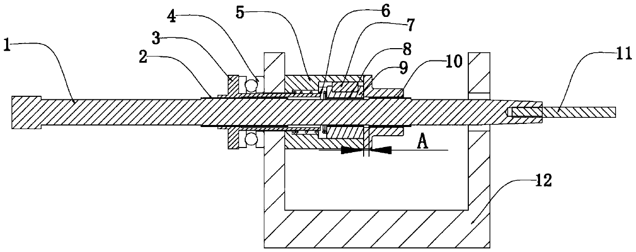
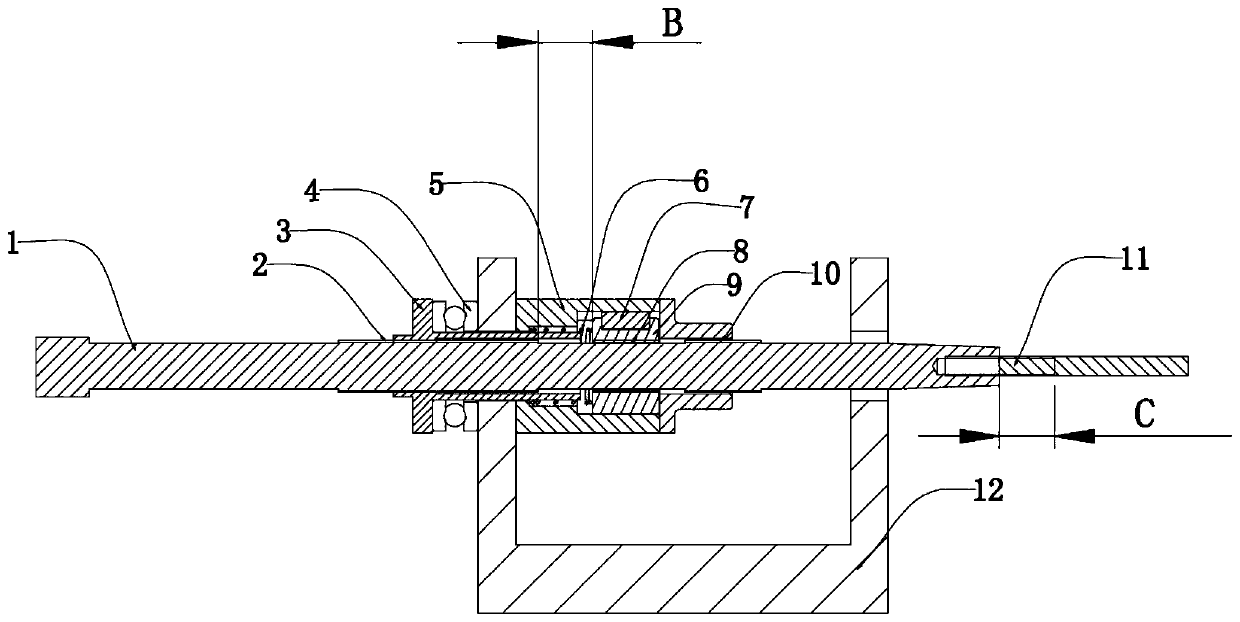
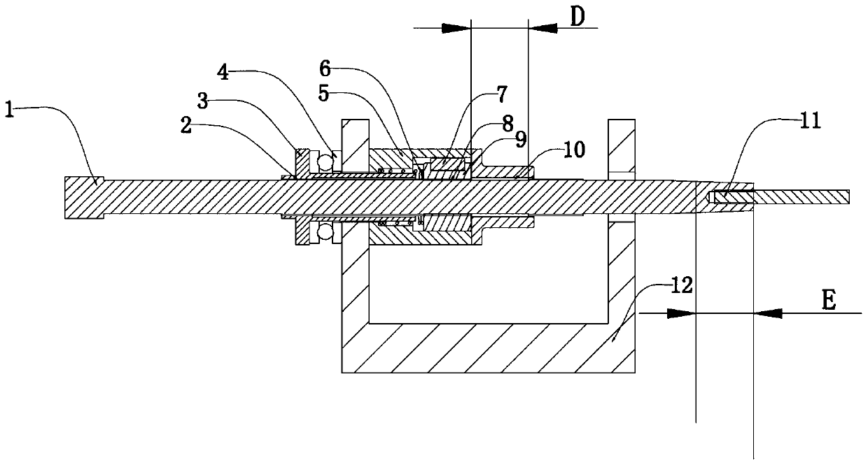
[0032] Please refer to Figure 1-3 , in this embodiment, the inner cavity of the guide seat 5 has a receiving cavity, and a retreat nut 9 is arranged in the receiving cavity, and a second screw thread 8 is provided on the inner cavity wall of the retracting nut 9; the tension rod 1 passes through the retracting Nut 9, during the retraction process of the tension rod 1, the side of the first thread 10 close to the second end will be threadedly connected with the second thread 8 on the retraction nut 9, so that the second thread of the tension rod 1 on the retraction nut 9 The thread 8 can be further retracted under the action of the thread, and finally the tension rod 1 is retracted outside the inner surface of the mould, avoiding manual secondary adjustment of the tension rod 1 .

[0033] On the basis of the above-mentioned embodiments, a guide key 7 is provided between the side wall of the retraction nut 9 and the accommodation cavity to prevent the rotation of the retraction...


PUM


Abstract

The invention discloses a tension relax device and tension relax method, and belongs to the technical field of rail transit infrastructure construction devices, the tension relax device comprises a tension-pull rod and a guide seat, wherein the tension-pull rod is provided with a first end and a second end; the first end is an operation end, and the first end can be connected with an operation piece to be tension relax; the second end is connected with a driving device and can drive the tension-pull rod to rotate through the driving device; the tension-pull rod is provided with first threads along the direction from the first end to the second end; the guide seat is internally provided with an inner cavity penetrating through the two ends, the tension-pull rod penetrates through the innercavity, at least a part of the inner cavity wall of the inner cavity is provided with second threads, and the second threads are in threaded connection with the first threads; after the tension-pull rod is separated from steel bar, the first threads of the tension-pull rod is in threaded connection with a retraction nut, so that the tension-pull rod can be continuously retracted out of the inner side surface of the die, so that the manual secondary adjustment of the tension-pull rod is avoided, so that the automation of the tension relax action is realized, the production efficiency is improved, and the production cost is reduced.

Description

technical field [0001] The invention relates to the technical field of rail transit infrastructure construction devices, in particular to a tensioning device and a tensioning method. Background technique [0002] The pre-tensioning method is to stretch the prestressed tendons before pouring concrete, and temporarily anchor the stretched prestressed tendons on the pedestal or steel form, and then pour the concrete until the concrete strength reaches no less than 80% of the concrete design strength value. When the prestressed tendons are guaranteed to have sufficient bonding with the concrete, the prestressed tendons are relaxed, and the prestressed concrete is applied to the concrete by means of the bonding between the concrete and the prestressed tendons. [0003] When using the pre-tensioning method to produce steel bars for high-speed railway ballastless track slabs, usually, the steel bars that have been stretched are connected to the tension rods through threads, and the...

Claims


Application Information

Patent Timeline
Patent Type & Authority Applications(China)
IPC IPC(8): B28B23/04
CPCB28B23/043
Inventor 孙春凤崔伟强綦锦涛魏猛唐立星赵平
Owner HIMILE MECHANICAL MFG
Why Eureka
Try Eureka