
Long-spray-pipe shock wave soot blower with functions of cooling and preventing soot accumulation

A shock wave soot blower and shock wave generator technology, applied in the field of long nozzle shock wave soot blowers, can solve the problems of shortening service life, affecting heat transfer, and dust accumulation, so as to prolong service life and achieve uniform distribution Effect

Pending Publication Date: 2019-07-30
CSIC SHANGHAI NEW ENERGY
View PDF0 Cites 0 Cited by
  • Summary
  • Abstract
  • Description
  • Claims
  • Application Information

AI Technical Summary

Problems solved by technology

[0008] Aiming at the deficiencies of the prior art, the present invention proposes a long-nozzle shock wave sootblower with the functions of cooling and preventing soot accumulation, which can not only solve the problem of dead corners and dead zones in the limited coverage area of ​​short-nozzle sootblowing, but also solve the problem of Soot accumulation, coking and clogging in the long nozzle of the shock wave soot blower, in the delivery pipe and in the generator; at the same time, it can also solve the problem that the long nozzle in the high-temperature flue cannot be cooled, shorten the service life, and introduce air to ignite Problems such as dust accumulation and affecting heat transfer

Method used


Image

  • Long-spray-pipe shock wave soot blower with functions of cooling and preventing soot accumulation
  • Long-spray-pipe shock wave soot blower with functions of cooling and preventing soot accumulation
  • Long-spray-pipe shock wave soot blower with functions of cooling and preventing soot accumulation

Examples


Embodiment

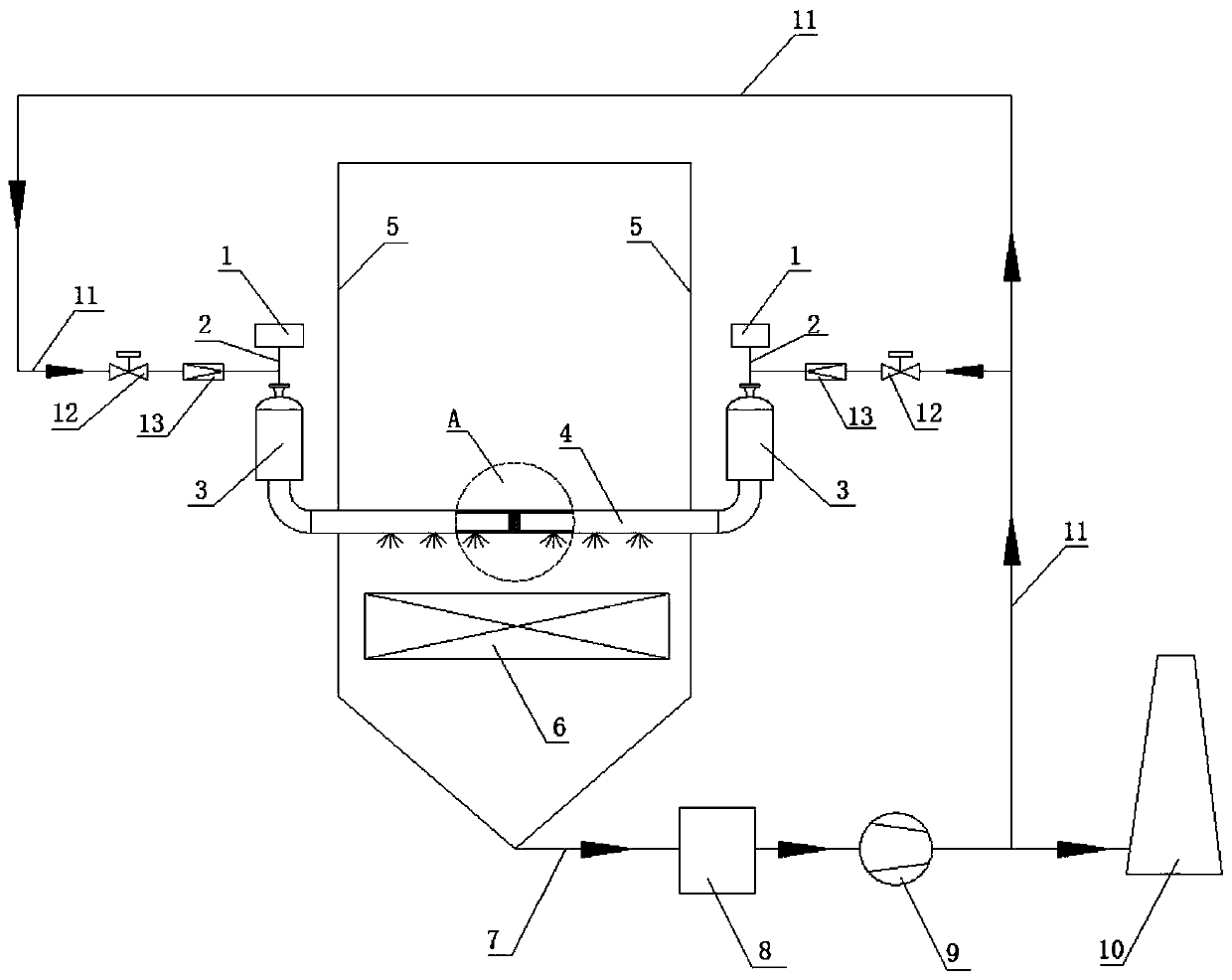
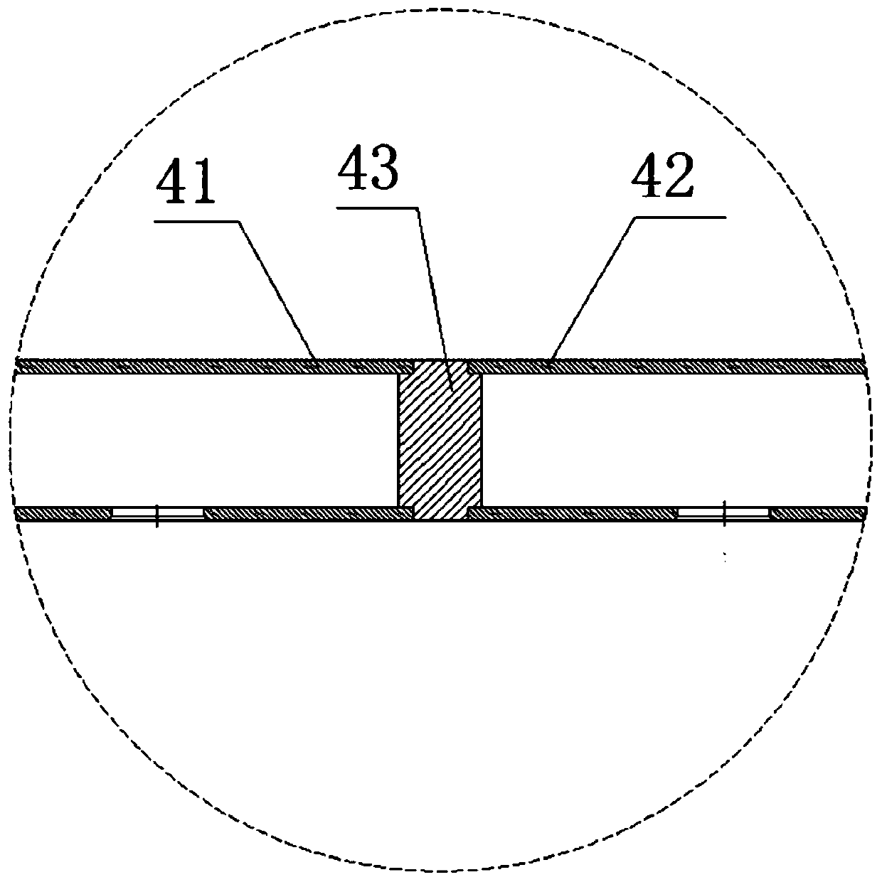
[0022] specific embodiment Figure 1 to Figure 3 As shown, the present invention includes a gas distribution ignition device 1, an ignition pipeline 2, a shock wave generator 3, a long nozzle 4, a furnace wall 5, a convective heat exchange tube bundle 6, a flue gas pipeline 7, a flue gas dust removal and purification system 8, an induction Fan 9, chimney 10, clean flue gas pipe 11, clean flue gas control valve 12, clean flue gas check valve 13, gas distribution ignition device 1 is connected with shock wave generator 3 through ignition pipe 2, and two shock waves are generated The device 3 is symmetrically arranged; the gas outlet of the shock wave generator 3 is connected with the gas inlet of the long nozzle 4, the long nozzle 4 runs through the furnace wall 5 and is arranged in the flue, and the long nozzle 4 consists of a left nozzle 41 which is left and right symmetrical. , the right nozzle 42 and the rigid connecting column 43 are welded, and the bottoms of the left and ...


PUM


Abstract

The invention discloses a long-spray-pipe shock wave soot blower with functions of cooling and preventing soot accumulation in the technical field of boiler soot blowing. The long-spray-pipe shock wave soot blower comprises a gas distribution ignition device, an ignition pipeline, a shock wave generator, a long spray pipe, a furnace wall, a flue gas pipeline, a flue gas dust removal purification system, an induced draft fan, a chimney, a clean flue gas pipeline, a clean flue gas control valve and a clean flue gas one-way valve. In the long-spray-pipe shock wave soot blower, the long spray pipepenetrates through the furnace wall and is arranged in a flue, multiple nozzles with gradually-changed sizes are symmetrically formed in the bottom of the long spray pipe, and uniform distribution ofthe soot blowing full-area coverage and the shock wave energy can be realized; the clean flue gas pipeline can introduce clean flue gas subjected to purification treatment into the shock wave generator, the negative pressure in the flue and the micro positive pressure at an outlet of the induced draft fan are utilized, continuous air inlet flow is formed in the shock wave generator and the long spray pipe, dust-containing flue gas is prevented from entering the long spray pipe and the shock wave generator, and the problems of forming soot accumulation, coking and blockage and the like are prevented; and meanwhile, the clean flue gas with relatively low temperature plays a certain cooling effect on the long spray pipe in the high-temperature flue.

Description

technical field [0001] The invention relates to a soot blower in the technical field of boiler soot blowing, in particular to a long soot blower with the functions of cooling and preventing dust accumulation that can prevent dust-laden fumes from entering into long nozzles, conveying pipes and shock wave generators. Nozzle shock wave sootblower. Background technique [0002] Various industrial boilers are widely used in the fields of energy and environmental protection, such as pulverized coal boilers, circulating fluidized bed boilers, waste heat furnaces, process furnaces, biomass boilers and waste incinerators. During the operation of these boilers, the heating surface of the convection tube bundle is generally prone to ash accumulation, which increases the resistance of the flue gas, the temperature of the exhaust gas increases, and the thermal efficiency of the boiler decreases, which seriously affects the normal operation of the boiler. [0003] Shock wave sootblower,...

Claims


Application Information

Patent Timeline
Patent Type & Authority Applications(China)
IPC IPC(8): F23J1/00F23J3/02
CPCF23J1/00F23J3/02F23J2700/001
Inventor 张冲梁鹏飞武超
Owner CSIC SHANGHAI NEW ENERGY
Learn More