
Method for measuring dynamic stiffness of flywheel bearing

A measurement method and dynamic stiffness technology, applied in measurement devices, elasticity testing, mechanical component testing, etc., can solve the problems of assembly characteristic damage, inability to real-time monitoring, waste of human and material resources, etc., to avoid disassembly and damage, save money To measure the effect of time and labor costs

Active Publication Date: 2019-07-23
DONGHUA UNIV
View PDF9 Cites 5 Cited by
  • Summary
  • Abstract
  • Description
  • Claims
  • Application Information

AI Technical Summary

Problems solved by technology

[0005] The problem to be solved by the present invention is: the existing method of measuring the dynamic stiffness of the flywheel bearing must disassemble the flywheel structure, which is easy to cause damage to the original assembly characteristics, and requires specific high-precision measuring equipment, resulting in unnecessary waste of manpower and material resources, and cannot monitor in real time The problem

Method used


Image

  • Method for measuring dynamic stiffness of flywheel bearing
  • Method for measuring dynamic stiffness of flywheel bearing
  • Method for measuring dynamic stiffness of flywheel bearing

Examples


Embodiment

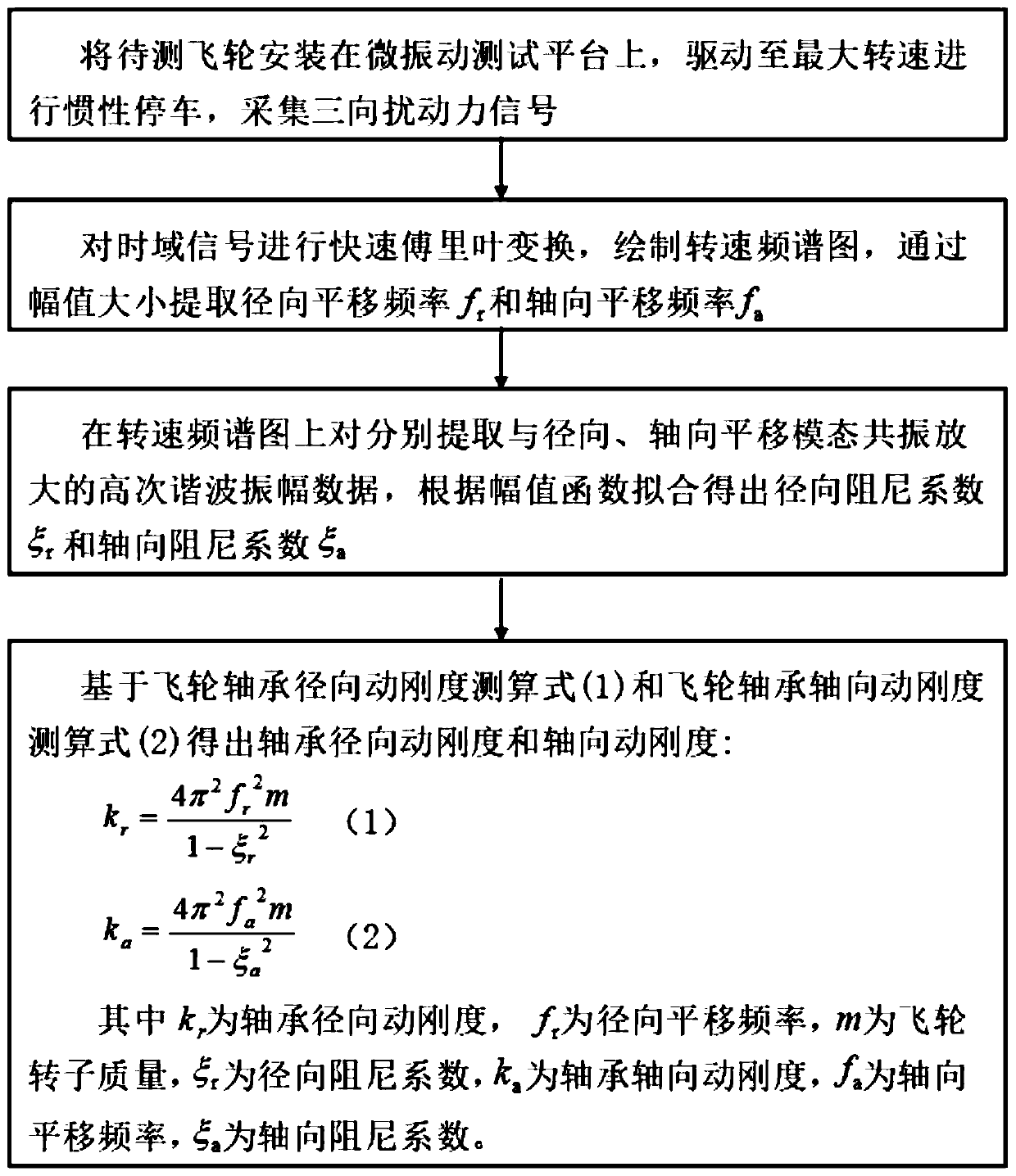
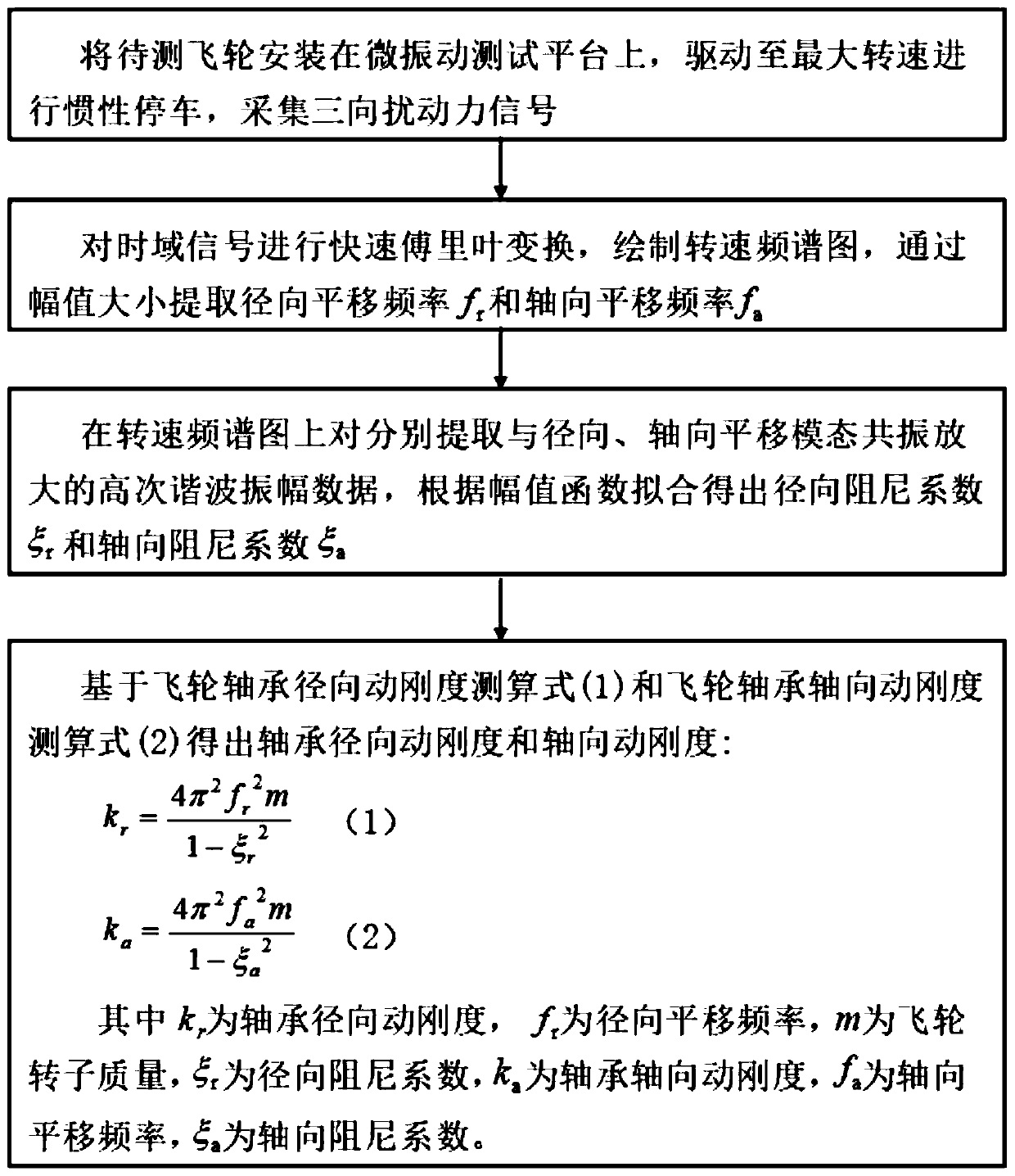
[0039] A method for measuring the dynamic stiffness of a flywheel bearing, such as figure 1 shown, including the following steps:

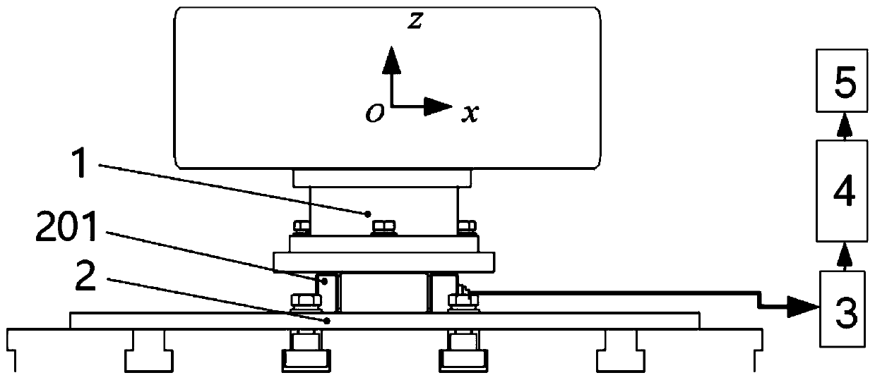
[0040] Step 1): Install the flywheel to be tested on the micro-vibration test platform, drive the flywheel to the maximum speed and perform inertial parking, and obtain the three-way disturbance force signal in the entire operating state through the acquisition system;

[0041] Step 2): Fast Fourier transform is performed on the collected time-domain signal, and the three-way rotational speed spectrum of the flywheel is drawn, and the radial translation frequency f of the rotor is extracted by the amplitude r = 400Hz and axial translation frequency f a = 232Hz;

[0042] Step 3): On the x (radial) and z (axial) rotational speed spectrograms, respectively extract the high-order harmonic amplitude data resonantly amplified with the radial and axial translation modes, and fit the data according to the amplitude function The radial damping coefficie...


PUM


Abstract

The invention discloses a method for measuring dynamic stiffness of a flywheel bearing. The method is characterized by comprising the following steps of installing a flywheel to be tested on a micro-vibration test platform, driving the flywheel to the maximum rotating speed and then carrying out inertial parking, and acquiring a three-way disturbing force signal in the entire operating state through an acquisition system; performing fast Fourier transform on an acquired time domain signal, drawing a flywheel three-way rotating speed spectrogram, and extracting the radial translation frequencyand the axial translation frequency of a rotor through the amplitude; respectively extracting high-order harmonic amplitude data resonated and amplified with radial and axial translational modals on x-direction and z-direction rotating speed spectrograms, and fitting the data to obtain a radial damping coefficient and an axial damping coefficient according to an amplitude function; and calculatingto obtain the radial dynamic stiffness and the axial dynamic stiffness of the flywheel bearing. According to the method for measuring dynamic stiffness of a flywheel bearing provided by the invention, dismounting and destruction of the structure can be avoided by adopting indirect measurement, and the method has the beneficial effects of being simple in calculation, non-invasive, and real-time and visual in results.

Description

technical field [0001] The invention relates to a method for measuring the dynamic stiffness of a flywheel bearing, belonging to the technical field of engineering measurement and calculation. Background technique [0002] Rotating machinery is one of the most widely used equipment in modern industry, and its condition monitoring and fault diagnosis have become the most critical parts in system design and maintenance. As a typical rotating machine, the flywheel consists of a moving rotor, supporting bearings, and a protective cover, and is mainly used for attitude control of spacecraft. When studying the flutter characteristics of satellites, it is often necessary to obtain the relevant characteristic parameters of the flywheel. [0003] Usually, the bearing stiffness of the flywheel is provided by the bearing manufacturer, and the common measurement method is to establish a stiffness measurement model based on the change of the force and the change of the corresponding dis...

Claims


Application Information

Patent Timeline
IPC IPC(8): G01M13/045G01M5/00
CPCG01M5/0075G01M13/045
Inventor 徐洋尹显波盛晓伟申妍
Owner DONGHUA UNIV
Learn More