Eureka AIR delivers breakthrough ideas for toughest innovation challenges, trusted by R&D personnel around the world.

Armor arrangement

a technology of armor and arrangement, applied in the field of ballistic armor, can solve the problems of large gaps formed between the tiles, impose turtle-like discomfort on the user, and the imbricated arrangement of discus-shaped tiles is not weight-optimized compared to sapi plates, so as to enhance the multi-hit capability of armor, enhance comfort and mobility for the wearer, and improve the multi-hit performance. , the effect of comfort and mobility

Active Publication Date: 2013-05-07
VERCO MATERIALS
View PDF49 Cites 20 Cited by
  • Summary
  • Abstract
  • Description
  • Claims
  • Application Information

AI Technical Summary

Benefits of technology

The present invention is about a flexible armor system that provides enhanced comfort and mobility for the wearer. The armor system utilizes a plurality of interlocking tiles made of ceramic and textile that can be adapted to different areas of coverage. The tiles have improved design and backing systems that enhance multi-hit performance and wearer comfort. The ceramic tiles have a strike face that undulates to deflect projectiles and induce them to turn on impact to further distribute energy. The tiles also have features on their reverse sides to facilitate interlocking and transmitting the energy of the projectile to other tiles for deflection and absorption. The invention can be used as a flexible armor arrangement or as a ballistic blanket for temporary structures and vehicles.

Problems solved by technology

The disadvantage of the SAPI plate is that it imposes a turtle-like discomfort for the user, and is unpredictable in second shot performance because of extensive random radial cracking often emanating from the point of impact of the first shot.
Consequently, large gaps are formed between the tiles when the armor flexes.
Furthermore, and an imbricated arrangement of discus-shaped tiles is not weight-optimized compared to a SAPI plate.

Method used


Image

  • Armor arrangement
  • Armor arrangement
  • Armor arrangement

Examples


Embodiment Construction

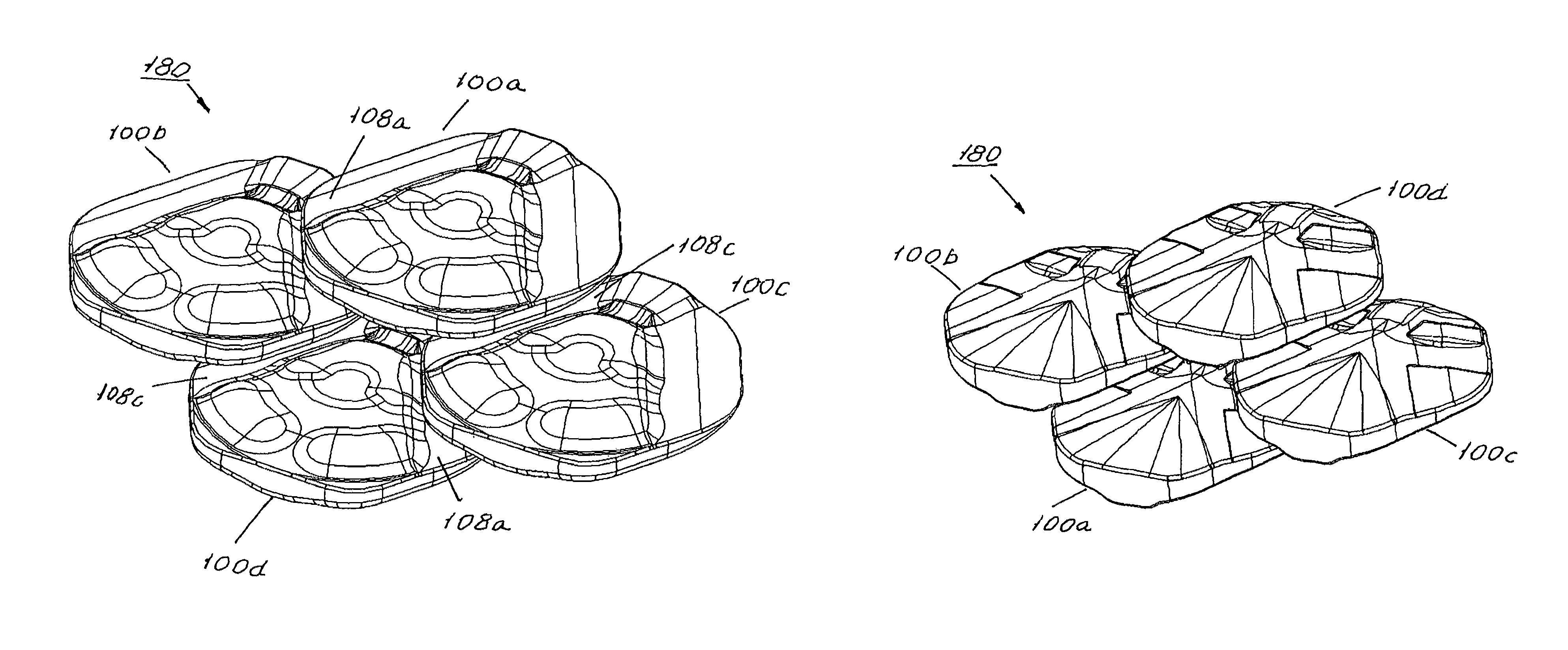
[0041]An armor system according to the present includes an assembly of ballistic tiles cooperatively arranged to provide a flexible body that may be fashioned into a body armor or any other type of armor capable of intercepting a high velocity projectile, e.g. a bullet from a firearm, and preferably a rifle shot. Preferably, the tiles may be identically shaped whereby a repeating pattern may be obtained through imbrication of the tiles or a like method to cover any area of a person's body, a vehicle or the like.

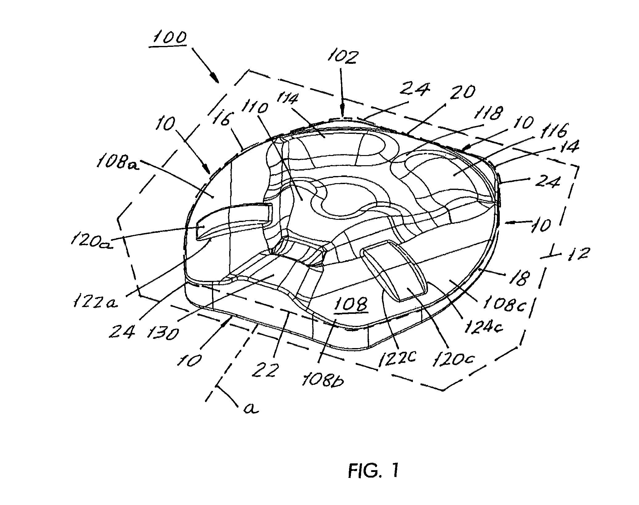
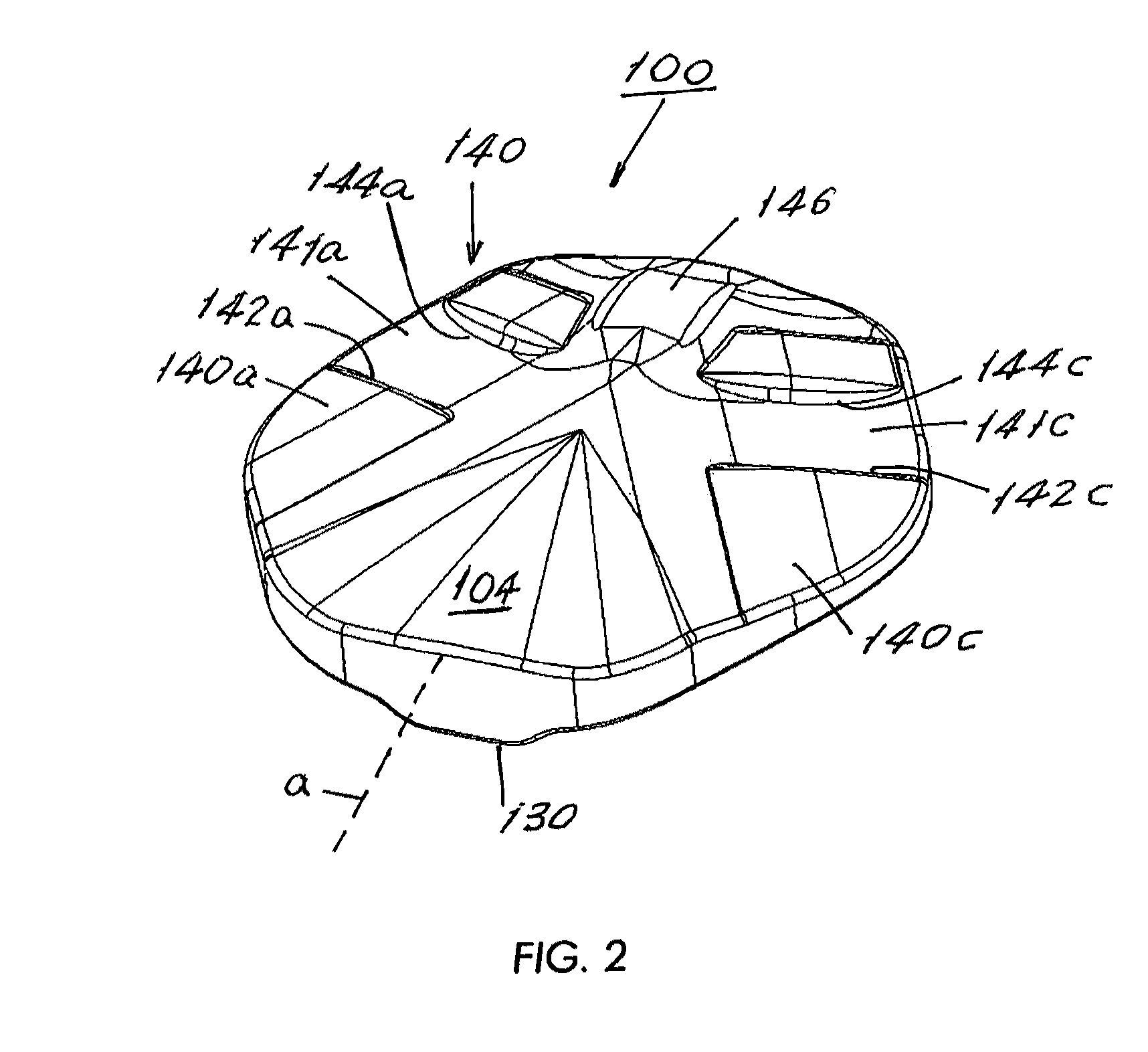
[0042]Referring now to FIG. 1, illustrated is a perspective view of a ballistic tile, generally 100, that may be used as a building block in an armor system according to a first embodiment of the present invention. FIG. 1 shows the obverse (i.e., front) side 102 of tile 100. FIG. 2 illustrates a perspective view of a reverse side 104 of the ballistic tile 100, which is opposite the obverse side 102 thereof.

[0043]A tile 100 according to the present invention is a single, unita...


PUM


Abstract

A ballistic tile for use in an imbricated pattern of like ballistic tiles to achieve coverage of a protected area by the imbricated pattern, while having rounded corners to limit the potential for spalling on ballistic impact. The ballistic tile may include a strike face that is generally undulating to laterally deflect at least a portion of the impact force, and to induce turning of the ballistic projectile on impact to further distribute the impact force. The ballistic tile may also include one or more features on an obverse and reverse side thereof that, when arranged in an imbricated pattern, limit lateral motion of the tiles on ballistic impact, and / or laterally transmit the energy of the projectile for deflection and absorption thereof.

Description

CROSS REFERENCE TO RELATED APPLICATION[0001]This application is based on and claims benefit of U.S. Provisional Application Ser. No. 61 / 175,349, filed on May 4, 2009, entitled BALLISTIC TILES. This application is also based on and claims benefit of U.S. application Ser. No. 12 / 220,190, filed on Jul. 22, 2008, entitled FLEXIBLE METHODS, SYSTEMS AND APPARATUSES FOR DEFEATING RIFLE AND HIGH VELOCITY PROJECTILES, which is based on and claims benefit of U.S. Provisional Application Ser. No. 60 / 961,610, filed on Jul. 23, 2007, entitled FLEXIBLE METHODS, SYSTEMS AND APPARATUSES FOR DEFEATING RIFLE AND HIGH VELOCITY PROJECTILES. A claim of priority is hereby made to the above applications and the contents of the above applications are specifically incorporated herein by reference.BACKGROUND OF THE INVENTION[0002]The present application relates to the field of ballistic armor, and more particularly to an armor arrangement that includes a plurality of ballistic tiles cooperatively arranged to...

Claims


Application Information

Patent Timeline
Patent Type & Authority Patents(United States)
IPC IPC(8): F41H5/06F41H5/08
CPCF41H1/02F41H5/0492F41H5/02F41H5/013
Inventor WILEY, CHARLES SCHENCKBAIN, ALLAN D.
Owner VERCO MATERIALS
Why Eureka
Eureka Blog
Learn More