Pressurization controllable oil injection device and oil injection method

An oil injection device and controllable technology, which is applied in the direction of lubricating oil control valves, lubricating pumps, lubricating parts, etc., can solve problems such as the inability to adjust the pressure of the oil injection system, the inability to accurately adjust the amount of oil injection, and the complexity of the cam manufacturing process. Achieve good atomization effect, good lubrication, and improve performance

Active Publication Date: 2021-07-13
SHENZHEN LOTUT INNOVATION DESIGN CO LTD
View PDF13 Cites 0 Cited by
  • Summary
  • Abstract
  • Description
  • Claims
  • Application Information

AI Technical Summary

Problems solved by technology

[0005] The traditional mechanical lubricator cannot adjust the pressure of the oil injection system circuit, and there is no way to accurately adjust the oil injection volume. The manufacturing process of the cam is complicated, and it is difficult to repair if it is worn out.
In response to the above problems, the Alpha oiler used by Man’s ME / MC diesel engine uses an electric oil pump to provide a high-pressure common rail servo oil source, and uses this oil source as power to control the oil source with a solenoid valve. When the solenoid valve is energized, the oil source Push a large piston to move, and the large piston pushes multiple small lubricating oil plungers, and these small lubricating oil plungers spray the lubricating oil to different nozzles respectively; when the solenoid valve is powered off, the large piston and the large piston are reset by the spring The lubricating oil plunger is reset. This device has flexible injection time and injection pressure. It is a better oil injection device. The patent "a common rail cylinder oil injection lubrication system" proposes to use the common rail injection principle to control the cylinder. The lubricating oil common rail pipe part realizes the adjustment of the lubricating oil supply pressure of the lubricating oil supply part of the cylinder according to the demand, and the control of the oil injection nozzle part realizes the adjustment of the lubricating oil injection time and the lubricating oil injection amount according to the demand. The flexible and flexible control of oil injection timing improves the control accuracy and control freedom. Although the above two devices have more flexible oil injection pressure and injection time, it is difficult to increase the oil injection pressure, and its structure is relatively complicated. Therefore, the present invention proposes A pressurized controllable oil injection device

Method used


Image

  • Pressurization controllable oil injection device and oil injection method
  • Pressurization controllable oil injection device and oil injection method

Examples


Embodiment 1

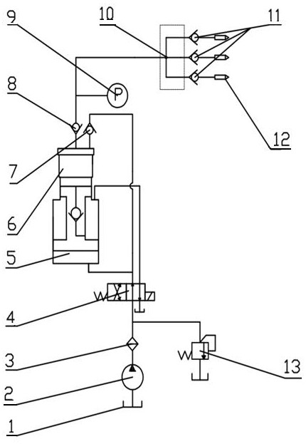
[0027] A pressurized and controllable oil injection device, which consists of: a constant pressure pump 2, the constant pressure pump is connected to the oil tank 1 and the filter 3 through pipelines, and the filter is connected to the safety valve through the pipelines 13. The two-position four-way electromagnetic reversing valve 4 is connected. The two-position four-way electromagnetic reversing valve is connected to the single-acting booster cylinder 5. The front end of the single-acting booster cylinder is connected to the front end cover 6 through threads. The front end cover is respectively connected to the one-way valve a7 and the one-way valve b8 through pipelines, the one-way valve a is connected to the two-position four-way electromagnetic reversing valve, and the one-way valve b is connected to the A pressure gauge 9 is installed between the shunts 10, and a one-way valve c11 is installed between the shunt and the oil injector 12. When the needle valve of the device ...

Embodiment 2

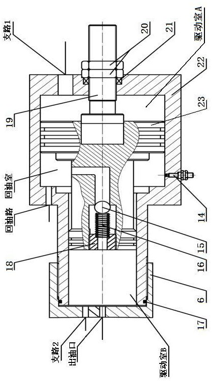
[0029] According to the pressurized controllable oil injection device described in Embodiment 1, the single-acting pressurized cylinder includes a cylinder body 22, and a piston body 23 is installed inside the cylinder body, and the piston body connects the inner part of the cylinder body. It is the driving chamber A, the oil return chamber and the driving chamber B. There are vertical intersecting holes on the circumference of the piston body, and a check valve 15 is installed at the front end of the vertical intersecting hole, and a check valve 15 is installed at the front end of the check valve. Spring 16, said spring is placed in the seam of limit sleeve 18, said piston body right end middle position is equipped with stroke adjusting screw rod 19, said stroke adjusting screw rod passes through the end face of said cylinder body, prevents The dust ring 21 is connected with the nut 20 through threads, a sealing ring 17 is installed in the groove at the front end of the cylind...

Embodiment 3

[0031] According to the pressurized controllable oil injection device described in Embodiment 1 or 2, the said splitter divides the oil circuit into a group of branches, and a group of said branches are respectively connected to the said one-way valve c, preventing The air in the oil nozzle of the oil injector enters the hydraulic circuit.


PUM


Abstract

The invention relates to a pressurization controllable oil injection device and an oil injection method. The traditional oil injector cannot adjust the pressure of the oil injection system circuit, and there is no way to accurately adjust the oil injection volume. The structure is relatively complicated, and it is difficult to increase the injection pressure. The composition of the present invention includes: a constant pressure pump (2), the constant pressure pump is respectively connected to the oil tank (1) and the filter (3) through pipelines, and the filter is respectively connected to the safety valve (13) and the two-position four-way through the pipeline The electromagnetic reversing valve (4) is connected, and the two-position four-way electromagnetic reversing valve is connected with the single-acting booster cylinder (5). It is connected with one-way valve a (7) and one-way valve b (8), one-way valve a is connected with two-position four-way electromagnetic reversing valve, and a pressure gauge is installed between one-way valve b and the shunt (10) (9), a one-way valve c (11) is installed between the splitter and the oil injector (12). The invention is used for a pressurized controllable oil injection device.

Description

Technical field: [0001] The invention relates to a pressurization controllable oil injection device and an oil injection method. Background technique: [0002] The lubricator is mainly used to regularly and quantitatively spray lubricating oil or grease to the friction parts of the mechanism, so as to ensure that the mechanism is always in a good lubrication state during the work of the mechanism, and reduce the wear and tear of the mechanism and power loss. The lubricator generally uses a high-pressure oil pump to provide the injection pressure of lubricating oil, and then uses various methods to regularly control the injection time to achieve regular injection; [0003] With the improvement of work requirements and environmental conditions, there are higher requirements for the injection pressure and injection time of the injector. Conditions can be adjusted to save lubricating oil and achieve the best lubricating effect; at the same time, in some applications, the fricti...

Claims


Application Information

Patent Timeline
Patent Type & Authority Patents(China)
IPC IPC(8): F16N7/38F16N13/16F16N23/00F16N29/00
CPCF16N7/38F16N13/16F16N23/00F16N29/00
Inventor 石勇严鹏
Owner SHENZHEN LOTUT INNOVATION DESIGN CO LTD
Why Eureka
Try Eureka