High-speed drive shaft oil-return device

A high-speed transmission and transmission shaft technology, which is used in the driving device, engine components, and engine lubrication of metal rolling mills. hood lock effect

Inactive Publication Date: 2013-12-25
XINJIANG BAYI IRON & STEEL
View PDF0 Cites 2 Cited by
  • Summary
  • Abstract
  • Description
  • Claims
  • Application Information

AI Technical Summary

Problems solved by technology

[0002] The internal gear lubricating oil of the main transmission shaft of the final stand of the finishing mill used in the hot rolling technology is often thrown out to the outside of the stand when the rolling mill is working, which wastes a lot and pollutes the working environment
Currently there is no effective tool to solve this problem

Method used


Image

  • High-speed drive shaft oil-return device
  • High-speed drive shaft oil-return device

Examples


Embodiment Construction

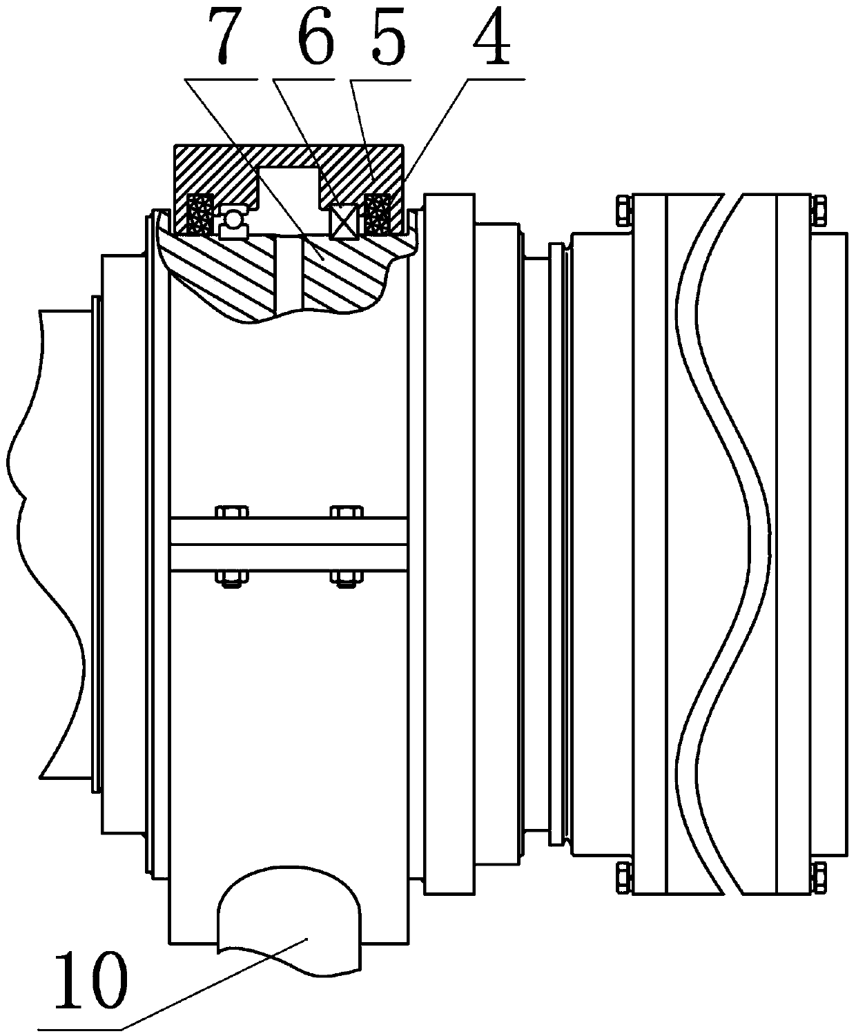
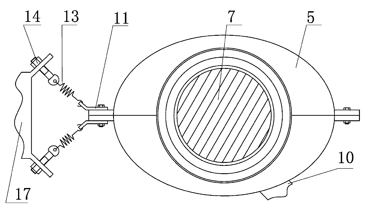
[0010] A high-speed transmission shaft oil return device, such as figure 1 , figure 2 As shown, the oil return device includes upper and lower halves of the oil return cover 5. The two halves of the oil return cover 5 are closed and wrapped in an oval shape on the outer periphery of the oil outlet section of the transmission shaft 7 of the rolling mill. The middle part of the two halves of the oil return cover 5 is concave Oil return tank, the oil return tank corresponds to the oil outlet section, the oil return covers on both sides of the oil return tank are respectively provided with bearings 6 and oil seals 4 from the inside to the outside, the bearings 6 are installed on the transmission shaft 7 of the rolling mill, and the oil return The bottom side of the cover 5 is provided with an oil return port 10, one side of the oil return cover 5 is connected together by bolts, and the other side of the oil return cover 5 is provided with an upper and lower ring 11 connected by b...


PUM


Abstract

The invention discloses a high-speed drive shaft oil-return device comprising an upper-half oil return cover and a lower-half oil return cover. The two half oil return covers are combined to be oval to wrap the outer peripheral edge of an oil outlet section of a rolling mill drive shaft, the middles of the two half oil return covers concave inwards to form an oil return chute corresponding to the oil outlet section, bearings and oil seals are arranged in the oil return covers on two sides of the oil return chute respectively from inside to outside, the bearings are mounted on the rolling mill drive shaft in a matched manner, an oil return port is formed in the side face of the bottom of the combined oil return cover, one sides of the oil return covers are connected together through bolts, an upper pull ring and a lower pull ring connected together though bolts are arranged on the other sides of the oil return covers, and the upper pull ring and the lower pull ring are respectively connected with an upper flange and a lower flange of a tension clamp through inclined tension springs. The high-speed drive shaft oil return device is capable of effectively collecting lubricating oil thrown out by a rolling mill, has an oil return function, and is simple in structure, stable in working and less prone to locking of the oil return covers and leakage.

Description

technical field [0001] The invention relates to a high-speed transmission shaft oil return device for a finishing mill. Background technique [0002] The internal gear lubricating oil of the main transmission shaft of the final stand of the finishing mill used in the hot rolling technology is often thrown out to the outside of the stand when the rolling mill is working, which is wasteful and pollutes the working environment. Currently there are no effective tools to solve this problem. Contents of the invention [0003] The purpose of the present invention is to provide a high-speed transmission shaft oil return device, which can effectively gather the lubricating oil thrown out by the rolling mill to realize the oil return function. It has a simple structure, stable operation, and is not prone to the problems of oil return cover locking and leakage . [0004] The object of the present invention is achieved in this way, a high-speed transmission shaft oil return device, ...

Claims


Application Information

Patent Timeline
Patent Type & Authority Applications(China)
IPC IPC(8): F16N31/02B21B35/14
Inventor 张智刚赵亮靳博邵辉
Owner XINJIANG BAYI IRON & STEEL
Why Eureka
Try Eureka