Heat pump system and control method for heat pump system

A heat pump system and control valve technology, applied in refrigerators, refrigeration components, refrigeration and liquefaction, etc., can solve the problems of high cost and increased power consumption, and ensure normal operation, avoid increased power consumption, and avoid higher costs. high effect

Active Publication Date: 2018-02-02
GREE ELECTRIC APPLIANCES INC
View PDF12 Cites 2 Cited by
  • Summary
  • Abstract
  • Description
  • Claims
  • Application Information

AI Technical Summary

Problems solved by technology

[0004] Embodiments of the present invention provide a heat pump system and a control method for the heat pump system to solve the problem of increased power consumption and high cost caused by the oil return solenoid valve installed in the heat pump system in the prior art

Method used


Image

  • Heat pump system and control method for heat pump system
  • Heat pump system and control method for heat pump system
  • Heat pump system and control method for heat pump system

Examples


Embodiment Construction

[0021] The present invention will be described in further detail below in conjunction with the accompanying drawings and specific embodiments, but not as a limitation of the present invention.

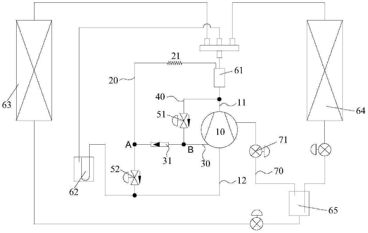
[0022] see figure 2 As shown, according to the embodiment of the present invention, a heat pump system is provided, including a variable capacity compressor 10, the exhaust port of the variable capacity compressor 10 communicates with the oil separator 61 through the exhaust pipeline 11, and the variable capacity compressor The air inlet of 10 communicates with the intake pipeline 12, the first end of the oil return pipeline 20 communicates with the oil outlet of the oil separator 61, the second end of the oil return pipeline 20 communicates with the intake pipeline 12, and the oil return pipeline 20 A throttling device 21 is provided on it.

[0023] In this embodiment, the heat pump system further includes a first control pipeline 30, a second control pipeline 40, a control valve 31...


PUM


Abstract

The present invention provides a heat pump system and a control method for the heat pump system, wherein the heat pump system includes a variable capacity compressor, a first control pipeline, and the first end of the first control pipeline is connected to the pressure switching port of the variable capacity compressor , the second end of the first control pipeline communicates with the oil return pipeline at the first node; the second control pipeline, the first end of the second control pipeline communicates with the exhaust pipeline, and the first end of the second control pipeline communicates with the exhaust pipeline. The two ends communicate with the first control pipeline at the second node, and the second control pipeline is provided with a first electromagnetic valve; the control valve, the control valve is arranged on the first control pipeline, and is located at the first node and the second node between the positions; the second electromagnetic valve is arranged on the oil return pipeline, and the second electromagnetic valve is located between the first node and the second end of the oil return pipeline. The invention effectively solves the problems of increased power consumption and high cost caused by the oil return electromagnetic valve provided in the heat pump system in the prior art.

Description

technical field [0001] The invention relates to the technical field of refrigeration, in particular to a heat pump system and a control method for the heat pump system. Background technique [0002] In the existing technology, such as figure 1 As shown, adding an oil separator 11' to the heat pump system can separate most of the lubricating oil carried by the exhaust in advance, and return it to the suction line 15 of the compressor 14' through the oil return capillary 12' and the oil return solenoid valve 13' ', prevent most of the lubricating oil from entering other system pipelines of the heat pump, improve the performance of the heat pump system, and ensure the height of the compressor lubricating oil level to avoid compressor oil shortage. [0003] However, setting the oil return solenoid valve in the heat pump system will lead to increased power consumption and higher costs. Contents of the invention [0004] Embodiments of the present invention provide a heat pump...

Claims


Application Information

Patent Timeline
Patent Type & Authority Patents(China)
IPC IPC(8): F25B1/00F25B31/00F25B41/04F25B49/02F25B41/20
Inventor 黄玉优吴永和
Owner GREE ELECTRIC APPLIANCES INC
Why Eureka
Try Eureka