
Transformer optical fiber detecting device

A technology of optical fiber detection and transformer, which is applied in the direction of using optical methods for testing, testing dielectric strength, and using acoustic measurement for testing, etc. It can solve the problems of low detection sensitivity, limited detection methods, and low sensitivity of piezoelectric ultrasonic sensors. Achieve accurate and effective partial discharge conditions, monitor partial discharge conditions, and avoid complexity

Inactive Publication Date: 2019-07-19
STATE GRID HEILONGJIANG ELECTRIC POWER CO LTD HARBIN POWER SUPPLY CO +1
View PDF8 Cites 0 Cited by
  • Summary
  • Abstract
  • Description
  • Claims
  • Application Information

AI Technical Summary

Problems solved by technology

[0002] At present, there are many methods for on-line monitoring of transformer partial discharge at home and abroad, mainly including very high frequency (VHF) pulse current detection method, ultra high frequency (UHF) electromagnetic wave detection method and piezoelectric sensor ultrasonic detection method, among which VHF and UHF detection method It is an electrical signal, which is easily interfered by electromagnetic interference signals; the piezoelectric ultrasonic method detects ultrasonic signals, but the sensor is attached to the equipment shell to detect ultrasonic signals generated by partial discharge inside the equipment, although it is not easily interfered by electromagnetic noise, but low sensitivity
There are also piezoelectric sensors placed inside the equipment casing to detect partial discharges in oil, but because piezoelectric ultrasonic sensors have low detection sensitivity in oil and cannot be placed at higher potentials for measurement, the detection method is limited. limit

Method used


Image

  • Transformer optical fiber detecting device
  • Transformer optical fiber detecting device
  • Transformer optical fiber detecting device

Examples


Embodiment Construction

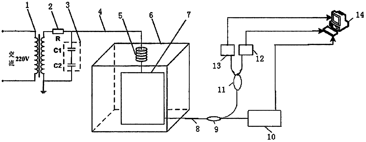
[0028] The following will clearly and completely describe the technical solutions in the embodiments of the present invention with reference to the accompanying drawings in the embodiments of the present invention. Obviously, the described embodiments are only some, not all, embodiments of the present invention. Based on the embodiments of the present invention, all other embodiments obtained by persons of ordinary skill in the art without making creative efforts belong to the protection scope of the present invention.

[0029] In order to make the above objects, features and advantages of the present invention more comprehensible, the present invention will be further described in detail below in conjunction with the accompanying drawings and specific embodiments.

[0030] Such as figure 1 As shown, a transformer fiber detection device provided in this embodiment is placed outside the power transformer 1, and the device mainly includes a plurality of fiber detection parts, a ...


PUM


Abstract

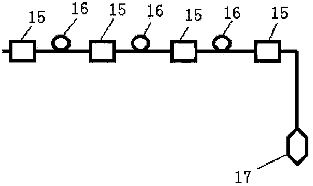
The invention discloses a transformer optical fiber detecting device and relates to the technical field of local discharge online monitoring of power transformers. The device is applied to power transformers and comprises an optical fiber detecting part, a first optical fiber coupler, a second optical fiber coupler and a controller; the primary side of the power transformer is connected to a mainssupply through a power line; the secondary side of the power transformer is connected with the optical fiber detecting part through a high-voltage lead; the first end of the first optical fiber coupler is connected with the optical fiber detecting part through a monomode optical fiber; the second end of the first optical fiber coupler is connected with the light source; the third end of the firstoptical fiber coupler is connected with the first end of the second optical fiber coupler; the second end and the third end of the second optical fiber coupler are connected with the controller separately through a photoelectric detector; and the optical fiber detecting part comprises optical fiber bragg grating F-P ultrasonic sensor or an optical fiber outer-cavity type fabry-perot sensor. The detecting device has features such has high sensitivity, strong signal collection capacity, convenient operation and strong capacity of resisting disturbance.

Description

technical field [0001] The invention relates to the technical field of on-line partial discharge monitoring of power transformers, in particular to a transformer optical fiber detection device. Background technique [0002] At present, there are many methods for on-line monitoring of transformer partial discharge at home and abroad, mainly including very high frequency (VHF) pulse current detection method, ultra high frequency (UHF) electromagnetic wave detection method and piezoelectric sensor ultrasonic detection method, among which VHF and UHF detection method It is an electrical signal, which is easily interfered by electromagnetic interference signals; the piezoelectric ultrasonic method detects ultrasonic signals, but the sensor is attached to the equipment shell to detect ultrasonic signals generated by partial discharge inside the equipment, although it is not easily interfered by electromagnetic noise, but The sensitivity is not high. There are also piezoelectric s...

Claims


Application Information

Patent Timeline
Patent Type & Authority Applications(China)
IPC IPC(8): G01R31/12
CPCG01R31/1209G01R31/1218
Inventor 范晓舟陈铁徐永峰杨明宇徐天时寻广朕刘云鹏
Owner STATE GRID HEILONGJIANG ELECTRIC POWER CO LTD HARBIN POWER SUPPLY CO
Learn More