
Quick positioning device for hardware processing

A positioning device and fast technology, applied in workpiece clamping devices, manufacturing tools, etc., can solve the problems of rigid damage to hardware products, lack of elastic protection mechanism for fixtures and workpieces, and lack of auxiliary locking and automatic reset mechanisms for positioning devices. It is convenient for locking and automatic reset, improving processing efficiency and avoiding rigid damage.

Inactive Publication Date: 2019-07-19
ZHONGSHAN FENGSHEN ELECTRICAL APPLIANCE CO LTD
View PDF0 Cites 2 Cited by
  • Summary
  • Abstract
  • Description
  • Claims
  • Application Information

AI Technical Summary

Problems solved by technology

[0004] 1. The structure of the general positioning device is relatively simple, and it is usually only suitable for a certain specification of hardware products. Therefore, in the actual use process, it is necessary to constantly replace the fixture according to the change of the product model, and finally have a negative impact on the processing efficiency of the hardware products.
[0005] 2. The existing positioning device lacks an efficient auxiliary locking and automatic reset mechanism, and the actual positioning device is difficult to operate
[0006] 3. The general positioning device adopts a direct clamping method inside, and there is no elastic protection mechanism between the clamp and the workpiece, so it is easy to cause rigid damage to hardware products due to excessive clamping

Method used


Image

  • Quick positioning device for hardware processing
  • Quick positioning device for hardware processing
  • Quick positioning device for hardware processing

Examples


Embodiment Construction

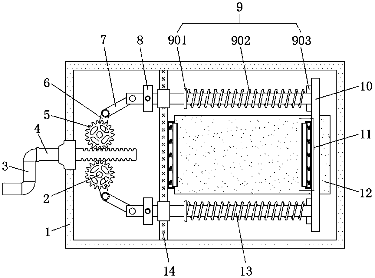
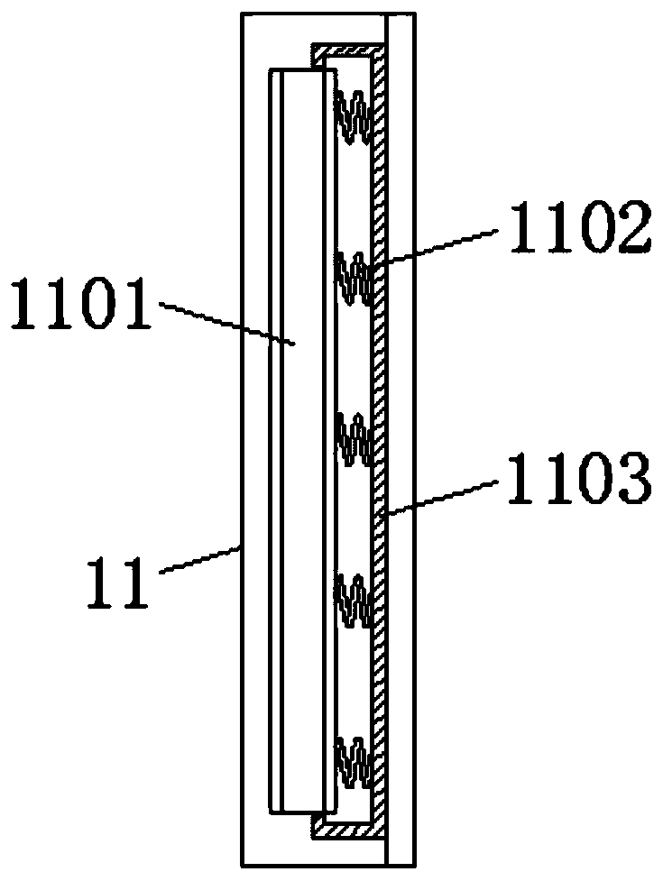
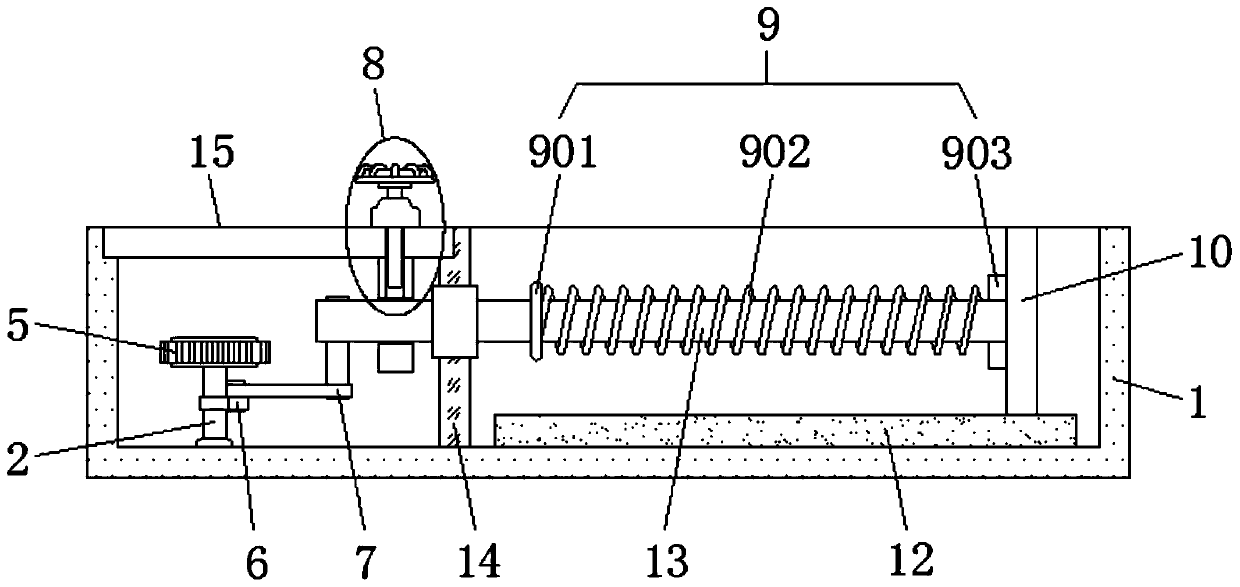
[0023] like Figure 1-Figure 4 As shown, a fast positioning device for metal processing includes a frame body 1, a locking mechanism 8, a reset mechanism 9, a buffer mechanism 11 and a sliding rod 13, and the center position of the left side wall of the frame body 1 is hinged with a threaded rod 4 through a bearing. And the left end of the threaded rod 4 is fixed with a rocker 3, the inside of the frame body 1 on both sides of the threaded rod 4 is hinged with a column 2, and the gear 5 at the top of the column 2 is meshed with the outer wall of the threaded rod 4, the middle of the column 2 Both are fitted with linkage rods 6, and the right ends of the linkage rods 6 are hinged with pull rods 7, the left side inside the frame body 1 is equipped with a fixed plate 14, and the top of the frame body 1 on the left side of the fixed plate 14 is snapped with a cover plate 15, Both sides inside the fixed plate 14 are hinged with slide bars 13 through bearings, and the left end of th...


PUM


Abstract

The invention relates to a quick positioning device for hardware processing. The quick positioning device for hardware processing comprises a frame body, a locking mechanism, resetting mechanisms, buffering mechanisms and sliding rods, wherein a threaded rod is hinged to the center of the left side wall of the frame body through a bearing; a rocking handle is fixed to the left end of the threadedrod; stand columns are hinged to the positions, in the frame body, on two sides of the threaded rod; linkage rods are arranged in the middles of the stand columns in a sleeving way; pull rods are hinged to the right ends of the linkage rods; a fixed plate is arranged on the left side in the frame body; a cover plate is clamped to the top part of the frame body on the left side of the fixed plate;the sliding rods are hinged to two sides in the fixed plate through bearings; the buffering mechanisms are arranged at the corresponding positions in the middles of a movable plate and the fixed plate; and the resetting mechanisms are arranged on the right parts of the sliding rods in a sleeving way. According to the quick positioning device for hardware processing, the processing efficiency of hardware products is improved, the operation difficulty of the positioning device is reduced, and the hardware products are prevented from being rigidly damaged.

Description

technical field [0001] The invention relates to the technical field of hardware processing devices, in particular to a fast positioning device for hardware processing. Background technique [0002] In the field of machinery manufacturing and processing, hardware products are widely used in the machinery manufacturing industry due to their superior practical performance. Among them, the main processes of hardware processing include cutting, stamping, welding, grinding, electroplating or oil injection, etc. In this process, it is necessary to use a positioning device of corresponding specifications for auxiliary clamping. [0003] However, there are still certain problems in the existing hardware processing positioning device, and the specific problems have the following points: [0004] 1. The structure of the general positioning device is relatively simple, and it is usually only suitable for a certain specification of hardware products. Therefore, in the actual use process...

Claims


Application Information

Patent Timeline
Patent Type & Authority Applications(China)
IPC IPC(8): B25B11/00
CPCB25B11/00
Inventor 余粉
Owner ZHONGSHAN FENGSHEN ELECTRICAL APPLIANCE CO LTD
Learn More