Al technical title is built by PatSnap Al team. It summarizes the technical point description of the patent document.
An output device, a technology of hot air flow, applied in hair drying devices, devices for washing hair or scalp, heating element materials, etc. The effect of fast heating rate and improved safety
Inactive Publication Date: 2020-06-05
TANWENG BEIJING TECH CO LTD
View PDF7 Cites 0 Cited by
Summary
Abstract
Description
Claims
Application Information
AI Technical Summary
This helps you quickly interpret patents by identifying the three key elements:
Problems solved by technology
Method used
Benefits of technology
Problems solved by technology
The heating elements of traditional hair dryers are generally metal materials. When the metal heating wire is heated, a large amount of electromagnetic radiation will be generated. When blowing hair, it will directly radiate to the head of the person, causing harm to the human body; in addition, the hair dryer must be in a dry environment. After using it for a long time, it will breed and accumulate a lot of bacteria, and it does not have antibacterial function
In addition, the temperature of the metal heating wire continues to rise, and the wind blowing out is getting hotter and hotter, which is likely to cause local burns
[0003] In the prior art, in order to improve the radiation caused by the heating principle of the metal electric heating wire to the human body, a ceramic heating element is installed between the heating element and the front nozzle of the air duct, but the carbon powder layer on the surface of the ceramic body will continue to fail, and it must be dried Use under certain conditions, the safety of use is greatly affected by the environment
Method used
Image
Click on the blue label to locate the original text in one second.
Reading with bidirectional positioning of images and text.
Examples
Embodiment 1
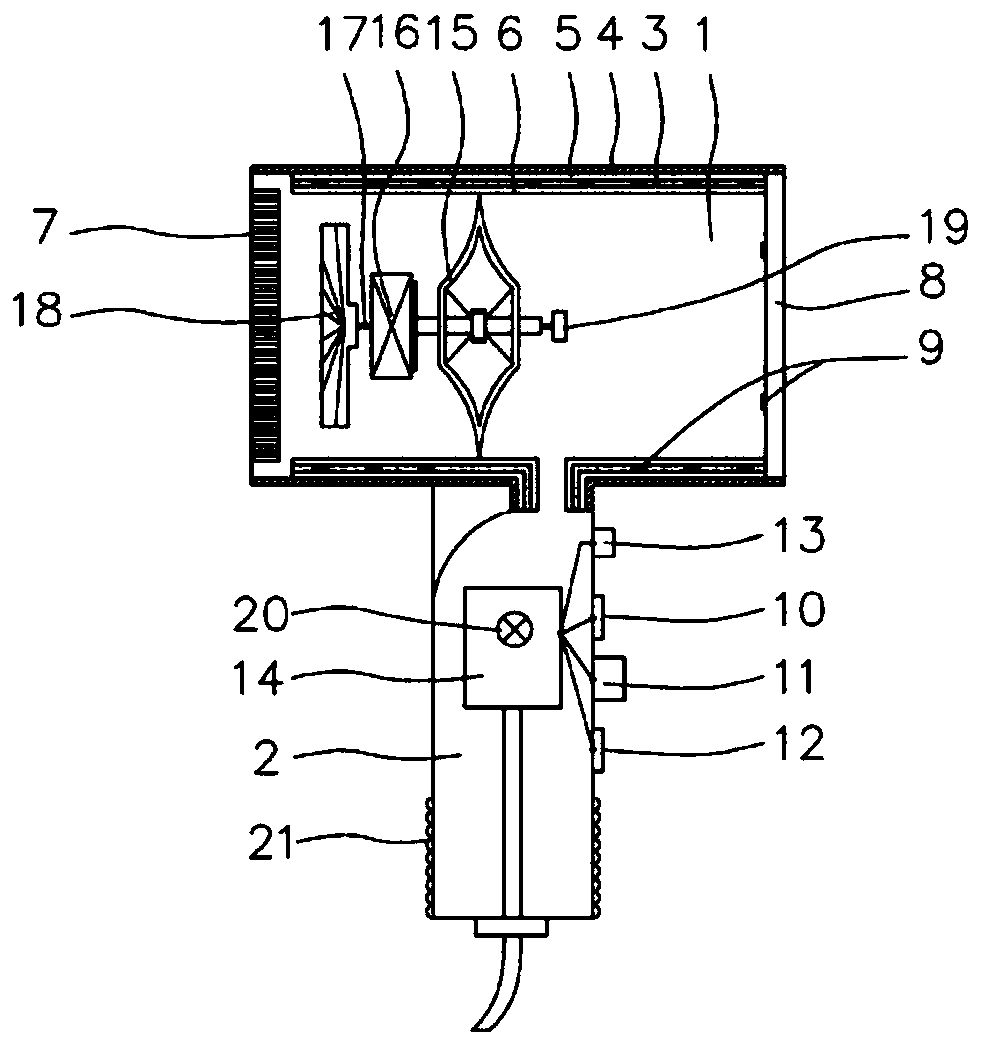
[0026] This embodiment describes a hand-held hot air output device, such as figure 1 As shown, the output device includes a housing 1 and a handle 2, the lower part of the housing 1 is connected to the handle 2, and the inner cavity communicates.
[0027] The left and right ends of the housing 1 are respectively provided with an air inlet cover 7 and an air outlet cover 8, and a heating part is provided on the side wall of the inner cavity of the housing 1 to radiate heat, and the air enters the inner cavity of the housing 1 through the air inlet cover 7 , is blown out by the air outlet cover 8 after being heated by the heating part. Shell 1 is made of high temperature resistant ABS (acrylonitrile-styrene-butadiene copolymer), PPS (polyphenylene sulfide), PC (polycarbonate), PA (polyamide), PP (polypropylene), HDPE (High-density polyethylene) and a series of polymer composite materials.
[0028] The heating part includes a heating element 3 , a reflection layer 4 , a heat in...
Embodiment 2
[0042] In a preferred embodiment, the heating element 3 adopts the self-made new heating element of the present invention, which is made of high-performance electrothermal material obtained from microcrystalline graphite directly grown on high-temperature-resistant fibers.
[0043] Specifically, the novel heating element of the present invention includes a high temperature resistant fiber layer and a microcrystalline graphite layer coated outside the high temperature resistant fiber layer.
[0044] The preparation method of electrothermal material usually includes the following steps:
[0045] Step 1: Prepare the cleaned fiber material;
[0046] Step 2: Carry out surface coating treatment on the fiber material, and the coated film layer contains a carbon source cracking catalytic material;
[0047] Step 3: Place the coated fiber material in a vacuum reaction chamber;
[0048] Step 4: feeding protective gas and reducing gas into the vacuum reaction chamber, and then feeding c...
PUM
Abstract
The invention relates to a handheld hot air flow output device, which comprises a shell and a handle. A heating part is arranged in the shell and comprises a heating element and temperature sensors; the heating element is made of a flexible carbon material, is arranged on the inner wall of an inner cavity of the shell, and comprises a high-temperature-resistant fiber layer and a microcrystalline graphite layer wrapping the high-temperature-resistant fiber layer; the multiple temperature sensors are evenly distributed in the heating element or on the inner side of an air outlet of the output device; the handle comprises an intelligent temperature control device which comprises a circuit control board and a microprocessor; the heating element and the circuit control board are connected, andthe temperature sensors are connected with the circuit control board through the microprocessor; the temperature sensors monitor the heating temperature of the heating element or the temperature situation of the inner cavity of the shell in real time, and transmit temperature information to the microprocessor; and the microprocessor adjusts the heating capacity of the heating element through the circuit control board. Preheating is not needed, heat dissipation is even, wind noise is small, safety performance is high, carrying is convenient, and the temperature is automatically adjusted.
Description
technical field [0001] The invention relates to a hot air output device, in particular to a hand-held hot air output device. Background technique [0002] Hair dryer products are commonly used electrical appliances in people's daily life. They are widely used in a large number. They are often used in hair care, laboratories, physiotherapy rooms, industrial production, art and other fields. The most important ones are applied to hair drying and stereotyped. The structure of the hair dryer is similar. It is generally composed of a shell, a handle, a motor, a fan blade, a heating element, a windshield, a switch, and a power cord. The working principle is that the motor drives the rotor to drive the fan blade to rotate. When the fan blade rotates, Air is sucked in from the air inlet, and the resulting centrifugal airflow is blown out by the front nozzle of the air cylinder. The heating elements of traditional hair dryers are generally metal materials. When the metal heating wi...
Claims
Application Information
Patent Timeline
Application Date:The date an application was filed.
Publication Date:The date a patent or application was officially published.
First Publication Date:The earliest publication date of a patent with the same application number.
Issue Date:Publication date of the patent grant document.
PCT Entry Date:The Entry date of PCT National Phase.
Estimated Expiry Date:The statutory expiry date of a patent right according to the Patent Law, and it is the longest term of protection that the patent right can achieve without the termination of the patent right due to other reasons(Term extension factor has been taken into account ).
Invalid Date:Actual expiry date is based on effective date or publication date of legal transaction data of invalid patent.