
Manufacturing method of amorphous metal thin-strip corrosion electrode

A technology of corrosion electrode and manufacturing method, applied in the direction of weather resistance/light resistance/corrosion resistance, measuring device, instrument, etc., can solve the problems of inability to weld wires in thin strips, bulk amorphous alloys, crystallization of thin strips, etc. Achieve the effect of reducing external interference, enhancing anti-corrosion performance and improving integrity

Active Publication Date: 2019-07-12
合肥名龙电子科技有限公司
View PDF13 Cites 0 Cited by
  • Summary
  • Abstract
  • Description
  • Claims
  • Application Information

AI Technical Summary

Problems solved by technology

[0003] At present, for the alloy system with weak amorphous forming ability, the existing experimental equipment cannot make large amorphous alloys, and the amorphous alloys prepared by the melt quenching method (single-roller stripping method or double-roller stripping method) The thickness of crystal alloy thin strips is only micron level. To test its corrosion behavior or study its corrosion mechanism by means of potentiodynamic polarization, the thin strips must be made into corrosion electrodes for accurate testing.
[0004] However, since the thickness of the amorphous thin strip is only micron level, the width is generally 3-5 mm; the thin strips of different alloy systems have different mechanical properties, and some thin strips are not only thin, but also very brittle, and do not infiltrate with solder , it is impossible to weld wires on the thin strip body; for the thin strip body soaked with solder, it may also cause the thin strip body to crystallize during the welding process, causing damage to the material; during the corrosion test, any tiny Vibration will cause a large jump in the signal

Method used


Image

  • Manufacturing method of amorphous metal thin-strip corrosion electrode
  • Manufacturing method of amorphous metal thin-strip corrosion electrode
  • Manufacturing method of amorphous metal thin-strip corrosion electrode

Examples


Embodiment

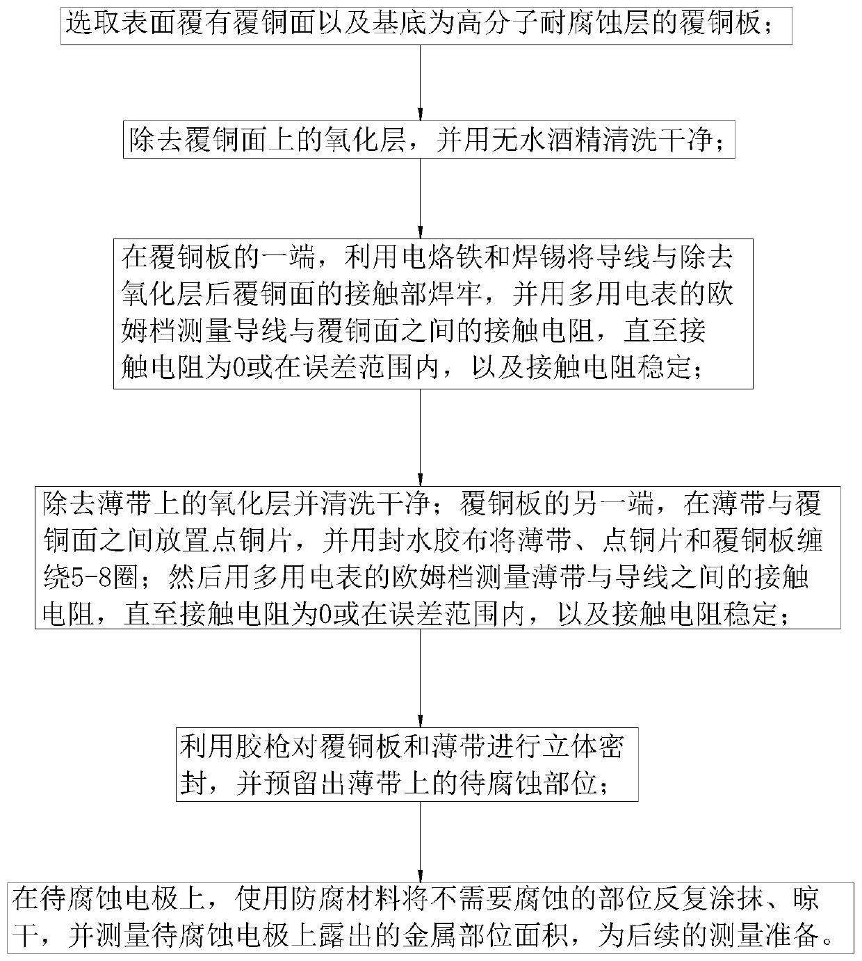
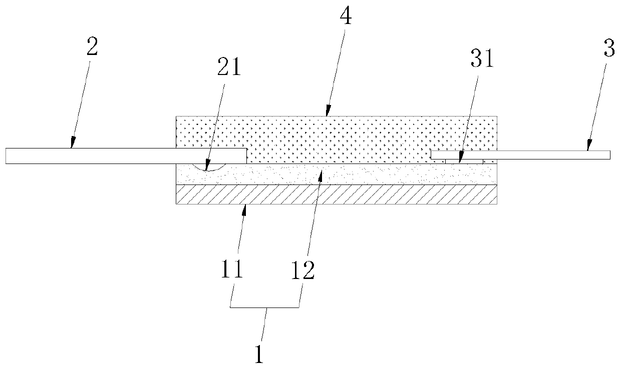
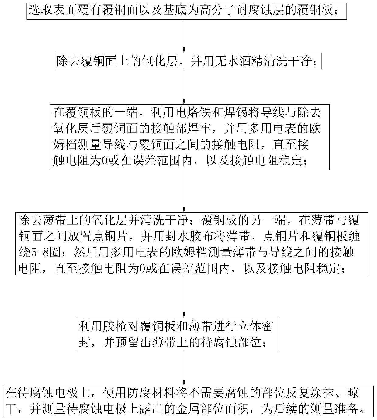
[0027] Embodiment: a kind of fabrication method of amorphous metal strip corrosion electrode, such as figure 1 and figure 2 shown, including the following steps:

[0028] Step 1, copper clad laminate 1 is selected. A copper-clad laminate 1 is selected whose surface is covered with a copper-clad surface 12 and whose substrate 11 is a polymer corrosion-resistant layer. The copper clad laminate 1 has a length of 40-60mm and a width of 5-10mm. In this embodiment, a single-sided circuit board with a length of 50 mm and a width of 8 mm is selected as the copper clad laminate 1 .

[0029] Step 2, the copper clad surface 12 is processed. Remove the oxide layer on the copper-clad surface 12, and clean it with absolute alcohol for 8-12 minutes. In this embodiment, the surface layer of the copper-clad surface 12 is polished with fine sandpaper, and cleaned with an ultrasonic cleaner in absolute alcohol for 10 minutes, so that the oxide layer of the copper-clad surface 12 is removed...


PUM

PropertyMeasurementUnit
Lengthaaaaaaaaaa
Widthaaaaaaaaaa

Abstract

The invention discloses a manufacturing method of an amorphous metal thin strip corrosion electrode, relates to the technical field of electrode corrosion, and solves the problems that in the existingelectrode corrosion, the stability of electric signal transmission is poor, a thin strip body is easy to damage, and an electric signal is easy to interfere by the outside. The technical solution isthat: selecting a copper-clad surface; removing the oxide layer on the copper-clad surface; firmly welding the wire and the contact part of the copper-clad surface; removing the oxide layer on the thin strip body, placing a point copper sheet between the thin strip body and the copper-clad surface, and winding the point copper sheet with a water-sealing adhesive tape; performing three-dimensionalsealing on the copper-clad plate and the thin strip body by using a glue gun, and reserving a to-be-corroded part; repeatedly smearing and air drying parts which do not need to be corroded by the anti-corrosion material, so that the effects of ensuring effective transmission of electric signals in electrode corrosion, ensuring the integrity of the thin strip body, preventing the thin strip body from shaking in corrosive liquid and reducing external interference on the electric signals are achieved. According to the patent, the invention is supported by the scientific and technical funds in Guizhou province.

Description

technical field [0001] The invention relates to the technical field of electrode corrosion, more specifically, it relates to a manufacturing method of an amorphous metal strip corrosion electrode. Background technique [0002] As a new metastable material, amorphous alloy (also known as metallic glass) has high strength, low elastic modulus, and excellent corrosion resistance compared with crystalline alloys of the same composition. Amorphous alloys are widely used in high-tech fields such as engineering, precision machinery, information, aerospace devices, and national defense industries, and become key materials for improving performance and developing military functionality. [0003] At present, for the alloy system with weak amorphous forming ability, the existing experimental equipment cannot make large amorphous alloys, and the amorphous alloys prepared by the melt quenching method (single-roller stripping method or double-roller stripping method) The thickness of cry...

Claims


Application Information

Patent Timeline
IPC IPC(8): G01N17/00
CPCG01N17/006
Inventor 吴学庆
Owner 合肥名龙电子科技有限公司
Learn More