An Integrator Circuit Applied to Ultraviolet Focal Plane Detector
A technology of integrating circuits and detectors, applied in the direction of logic circuit interface devices, logic circuit connection/interface layout, instruments, etc., can solve the problems of leakage current affecting the integration result of the integration circuit, narrow output voltage range, and the influence of the integration result, etc., to achieve Reduced leakage current, increased output voltage range, and high linearity
- Summary
- Abstract
- Description
- Claims
- Application Information
AI Technical Summary
Problems solved by technology
Method used
Image
Examples
Embodiment 1
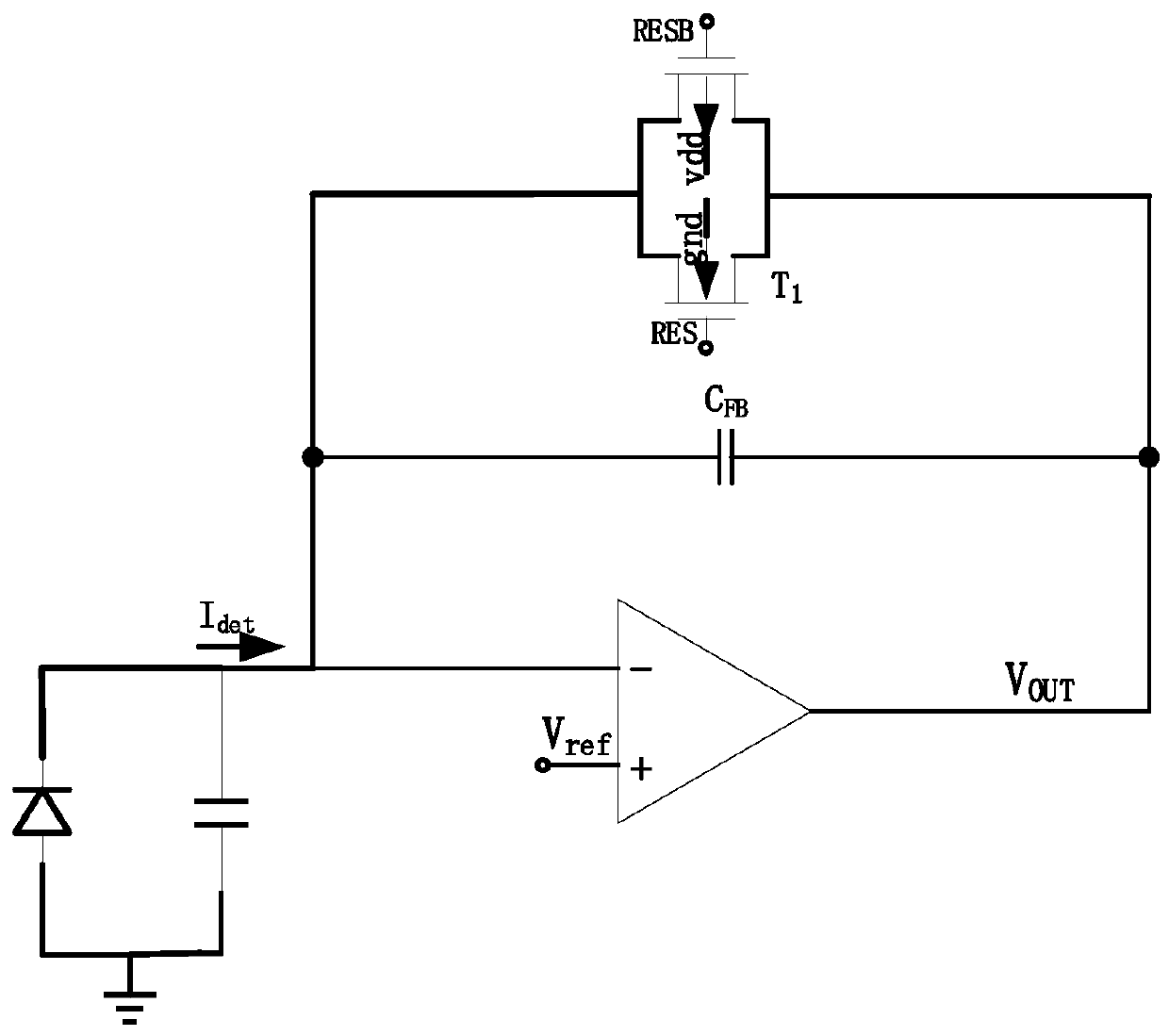
[0021] The traditional integrating circuit applied to the ultraviolet focal plane detector includes an operational amplifier, an integrating capacitor C FB and reset transmission gate T2, as figure 1 As shown; the working principle of the traditional integrating circuit is: in the process of integrating, reset the transmission gate T 2 disconnected, the UV focal plane detector photocurrent passes through the integrating capacitor C FB Carry out integral amplification and convert it into a voltage signal; in the reset process, reset the transmission gate T 2 conduction, the integrating capacitor C FB Do a reset. In the integration process of the traditional integration circuit, the integration capacitor performs integration and amplification of the photocurrent signal, and the reset circuit stops working. However, because the reset switch is not an ideal switch, even if the switch is turned off, there will still be current flowing through it. This part of the current Theref...
Embodiment 2
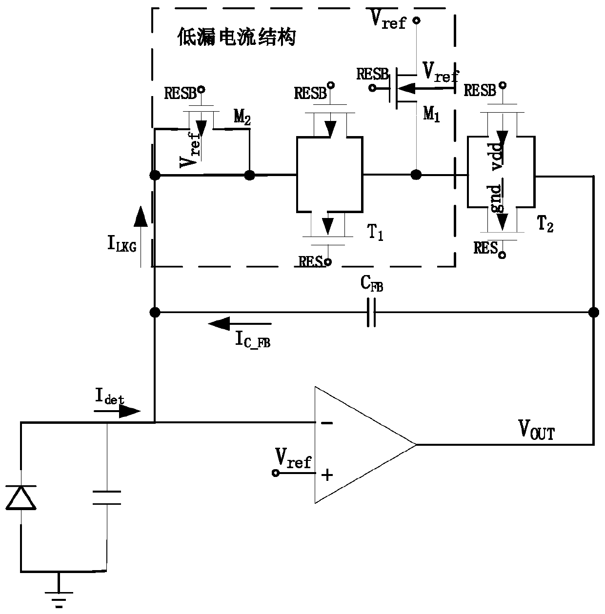
[0025] Based on Embodiment 1, in this implementation, the bulk terminal voltage of the transistor M1 and the transistor M2 is V ref ; The source voltage of the transistor M1 is V ref , the gate is connected to the reverse control signal RESB, and the drain is connected to the transmission gate T1; the source and drain of the transistor M2 are both connected to the transmission gate T1, and the gate is connected to the reverse control signal RESB; the transmission gate T1 The gate of one transistor is connected to the control signal RES, the gate of the other transistor is connected to the reverse control signal RESB, and the transistor body terminals in the transmission gate T1 are connected to their respective source terminals, such as figure 2 shown.
[0026] During the integration process, the integral capacitor performs integral amplification on the photocurrent signal, and the reset circuit stops working. However, since the reset switch tube is not an ideal switch tube,...
Embodiment 3
[0028] Based on the above-mentioned embodiment 2, such as figure 2 As shown, the integration circuit of this embodiment also includes a reset transmission gate T2, and the reset circuit is formed by the reset transmission gate T2 and a low leakage current structure, such as figure 2 shown. The reset transmission gate T2 is connected between the output terminal of the operational amplifier and the drain of the transistor M1; and the body terminal of one of the transistors in the reset transmission gate T2 is connected to the voltage vdd, and the gate is connected to the reverse control The signal RESB, the body terminal of another transistor is connected to gnd, and the gate is connected to the control signal RES. like figure 2 As shown, the shown reset transmission gate T2 is composed of a PMOS transistor and an NMOS transistor, and the body terminal of the PMOS transistor is connected to the power supply vdd, and its gate is connected to the reverse control signal RESB; ...
PUM
 Abstract
Description
Claims
Application Information
 - R&D Engineer
- R&D Manager
- IP Professional
- Industry Leading Data Capabilities
- Powerful AI technology
- Patent DNA Extraction
Browse by: Latest US Patents, China's latest patents, Technical Efficacy Thesaurus, Application Domain, Technology Topic, Popular Technical Reports.
© 2024 PatSnap. All rights reserved.Legal|Privacy policy|Modern Slavery Act Transparency Statement|Sitemap|About US| Contact US: help@patsnap.com


