
Venturi type micro-bubble generator and gas-liquid reactor

A micro-bubble generator and Venturi technology, applied in fluid mixers, chemical instruments and methods, mixers, etc., can solve the problems of discrete bubble size, high manufacturing difficulty, and high energy consumption, and achieve reduced bubble size, Simple structure and low energy consumption

Inactive Publication Date: 2019-07-05
ZHEJIANG UNIV
View PDF6 Cites 18 Cited by
  • Summary
  • Abstract
  • Description
  • Claims
  • Application Information

AI Technical Summary

Problems solved by technology

However, the smaller the particle size of the air bubbles, the smaller the pore size of the medium is required, and the requirements for the manufacturing and processing of the device are relatively high, and it is easy to cause blockage
[0006] To sum up, the existing micro-bubble generation devices have disadvantages such as difficult manufacturing, discrete bubble sizes, and high energy consumption.

Method used


Image

  • Venturi type micro-bubble generator and gas-liquid reactor
  • Venturi type micro-bubble generator and gas-liquid reactor
  • Venturi type micro-bubble generator and gas-liquid reactor

Examples


Embodiment 1

[0042] This embodiment adopts as figure 1 The microbubble generating device shown is used to prepare microbubbles, wherein the trapezoids of the spiral inner member are arranged in four rows, and the number of trapezoids in each row is 10. Each trapezoid is 3mm wide and 1mm high, and the top of the spiral inner member is 26mm long. , the bottom is 22mm long. Air is used as the gas experiment medium, and water is used as the liquid experiment medium. Air velocity at the air inlet u g =0.24m / s, liquid velocity u at the throat l From 0.32m / s to 2-5 times equivalent increase to 1.6m / s, using a high-speed camera to shoot the bubbles generated by the microbubbles, the microbubble fraction obtained by statistics changes with the liquid velocity as follows Figure 8 As shown, it can be seen from the figure that when the throat liquid velocity u l The larger , the higher the microbubble fraction η, when the liquid velocity u at the throat l =0.96m / s, microbubble fraction η=58%.

Embodiment 2

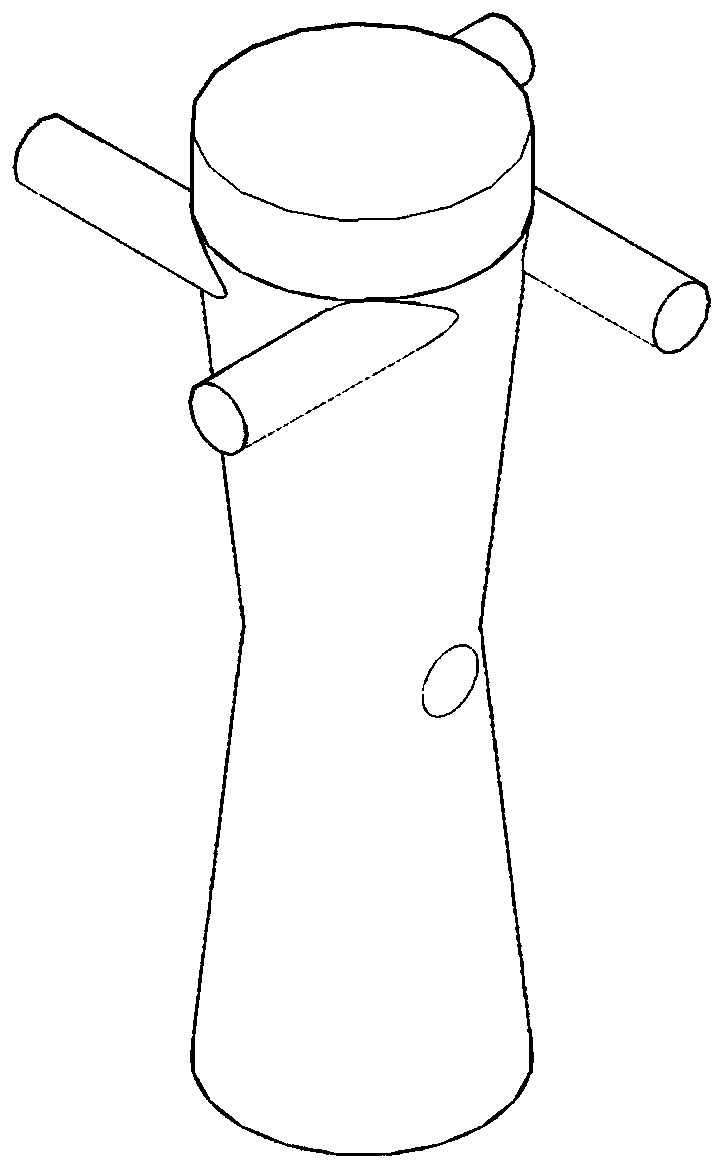
[0044] use as image 3 The shown microbubble generator includes a spiral internal member 1 , a converging section 2 , a throat section 3 , an air inlet 4 , a diverging section 5 and a tangential pipe 6 . The total length of the microbubble generator is 95mm, of which the length of the tapering section and the expanding section are both 40mm, the length of the throat is 0mm, and the length of the developing section is 15mm. The diameter of the outlet of the diverging section is equal to the diameter of the inlet of the tapering section, both of which are 26mm. A circular air intake hole with a diameter of 6mm. The spiral inner members are arranged in four rows, with a height of 20mm and a rotation angle of 90°. There are 10 trapezoids in each row. Each trapezoid is 2mm high and 3mm wide. The top of the spiral internal member is 26mm long and the bottom is 22mm long. The number of tangential outlet pipes is 4, the diameter is 6mm, and the length is 30mm.

[0045] Taking the a...

Embodiment 3

[0047] The only difference from Example 2 is that the gas velocity u at the air inlet g =0.36m / s, use a high-speed camera to shoot the bubbles generated by the microbubble generator, when the liquid velocity at the throat u l =0.96m / s, microbubble fraction η=71%.


PUM


Abstract

The invention discloses a Venturi type micro-bubble generator and a gas-liquid reactor, and belongs to the field of micro-bubble generators. The purpose of the invention is to overcome the disadvantages of large manufacturing difficulty, discrete bubble size and high energy consumption in the prior art. The Venturi type micro-bubble generator is composed of a swirling device, an air inlet hole anda Venturi tube, and the Venturi tube sequentially least comprises a converging section, a Venturi tube section and a diverging section from bottom to top. The Venturi type micro-bubble generator hasthe advantages of compact structure, low energy consumption, good micro-bubble generation effect, and convenience in maintenance. After the micro-bubble generator is used in the gas-liquid reactor, the gas-liquid mass transfer efficiency is greatly improved.

Description

technical field [0001] The invention relates to the field of petrochemical industry, in particular to a Venturi type microbubble generator and a gas-liquid reactor comprising the microbubble generator. Background technique [0002] Microbubbles have the characteristics of large specific surface area, high gas holdup, slow rising speed and fast dissolution speed. They are an important means to enhance mass transfer and are widely used in the mass transfer process between gas-liquid two phases in the petrochemical industry and wastewater treatment. , Brewing and aerobic biological farming and other fields. At present, the occurrence of microbubbles is mainly realized by microbubble generators. The generation methods are mainly divided into shear contact type, such as Venturi type microbubble generator; dissolved air release type, such as pressure dissolution type microbubble generator; Gas type, such as microporous plastic, rubber and ceramic tubes, etc.; ultrasonic foaming t...

Claims


Application Information

Patent Timeline
IPC IPC(8): B01F3/04B01F5/04B01J4/00B01J19/00
CPCB01J4/002B01J19/00B01J2204/002B01F23/23B01F25/3121B01F25/31242B01F2101/2204
Inventor 黄正梁王欣妍孙婧元杨遥张浩淼帅云郭晓云蒋斌波廖祖维王靖岱阳永荣
Owner ZHEJIANG UNIV
Learn More