Electrode for potential detection of electromagnetic flowmeter

An electromagnetic flowmeter and potential detection technology, which is used in the application of electromagnetic flowmeters to detect fluid flow, volume/mass flow generated by electromagnetic effects, measurement flow/mass flow, etc. Issues such as applying shock

Active Publication Date: 2019-06-25
YAMATAKE HONEYWELL CO LTD
View PDF11 Cites 0 Cited by
  • Summary
  • Abstract
  • Description
  • Claims
  • Application Information

AI Technical Summary

Problems solved by technology

[0003] However, when abrasive objects are mixed into the fluid flowing through the measuring tube, the noble metal material covering the electrodes may be peeled off.
In addition, the noble metal material covering the electrodes may be peeled off due to impacts applied to the measuring tube, corrosion of the measuring tube, defects during manufacturing, etc.

Method used


Image

  • Electrode for potential detection of electromagnetic flowmeter
  • Electrode for potential detection of electromagnetic flowmeter
  • Electrode for potential detection of electromagnetic flowmeter

Examples


no. 1 approach

[0033] Below, refer to Figure 1 to Figure 5 One embodiment of the electrode for potential detection of the electromagnetic flowmeter of the present invention will be described in detail. The electrode for potential detection of the present embodiment is an example of the electrode for potential detection described in claim 1 and claim 3 .

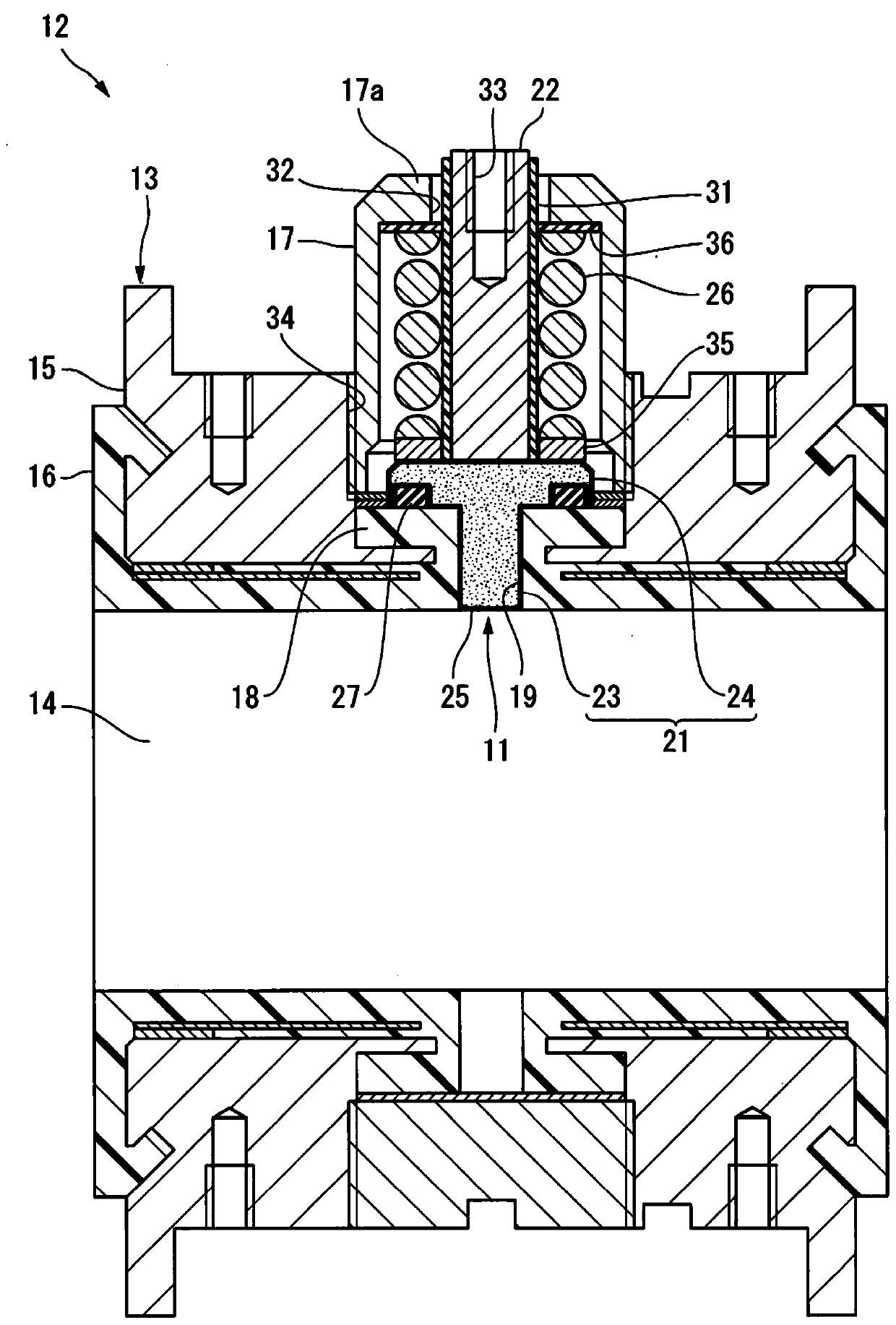
[0034] figure 1 The shown potential detection electrode 11 (hereinafter simply referred to as the electrode 11 ) is attached to the measurement tube 13 of the electromagnetic flowmeter 12 from the outside of the fluid passage 14 .

[0035] The measuring tube 13 includes a main body 15 , a liner 16 provided on the inner surface of the main body 15 , a bottomed cylindrical electrode cap 17 for accommodating the electrode 11 , and the like. The electrode mount 18 is integrally provided on the liner 16 . An electrode insertion hole 19 into which the electrode 11 is inserted is perforated in the electrode mount 18 .

[0036] The electrode ...

no. 2 approach

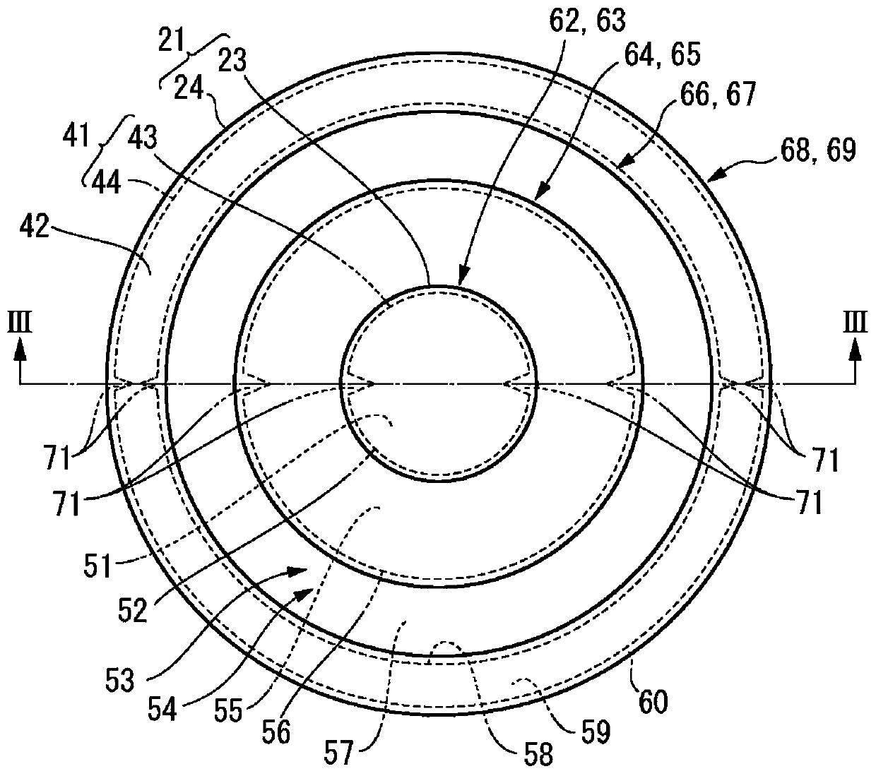
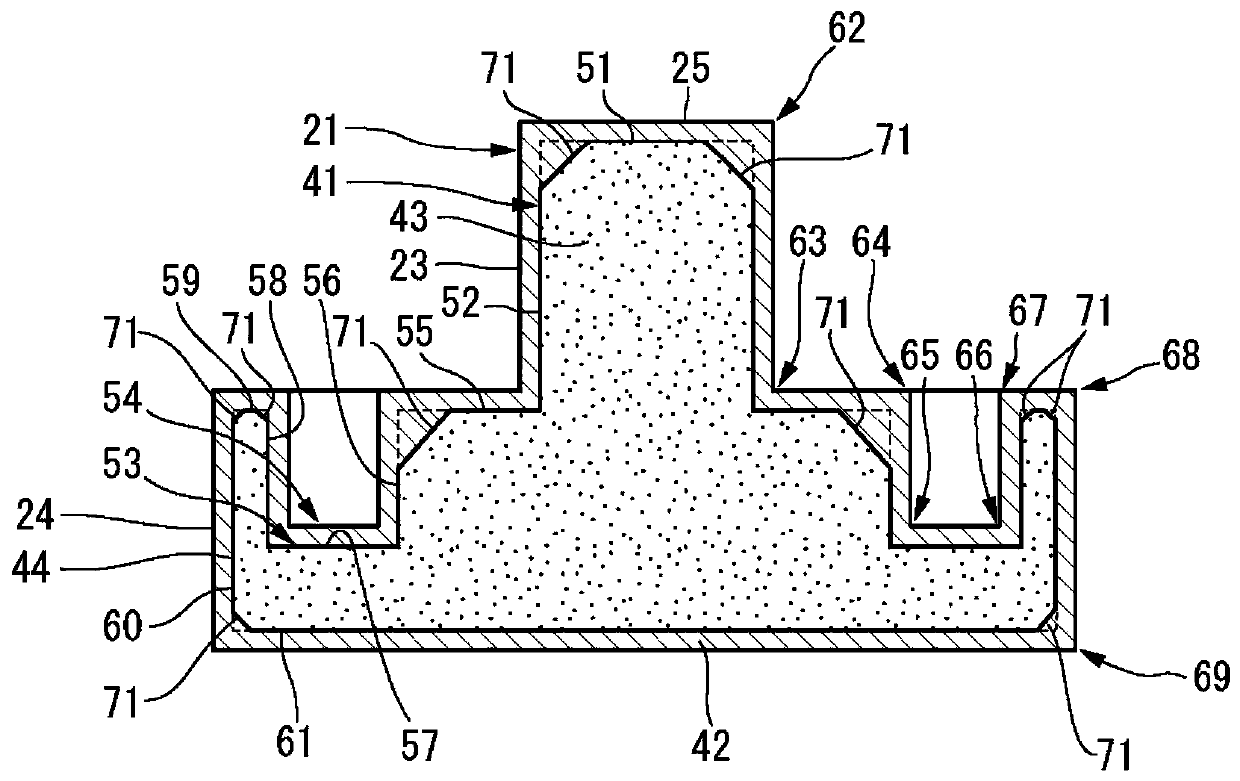
[0066] Slot can be as Figure 6 ~ Figure 8 constructed as shown. exist Figure 6 ~ Figure 8 in, for with Figure 1 to Figure 5 Members that are the same as or equivalent to those described will be given the same reference numerals, and detailed descriptions will be appropriately omitted. The electrode for potential detection of the present embodiment is an example of the electrode for potential detection described in claim 2 .

[0067] The groove 71 in this embodiment extends continuously along the outer surface of the base material 41 from the first end surface 51 at one end in the axial direction of the base material 41 to the fifth end surface 61 at the other end in the axial direction. In detail, the groove 71 extends along the first side surface 52 in the axial direction of the base material 41 to the other end side of the main body portion 21 with one end open on the first end surface 51 of the base material 41 , and radially transversely. Cut the second end surface ...


PUM


Abstract

Provided is an electrode for potential detection of an electromagnetic flowmeter, whereby electrical conductivity required for potential detection can be ensured at a corner regardless of the properties of a metal slurry, despite having a corner at which the thickness of a conductor produced by sintering the metal slurry becomes thinner. The electrode is provided with a main body part (21) which has a liquid contact part (25) and is formed by covering a base material (41) with an electric conductor (42), the liquid contact part being exposed to a measurement tube (13); and a terminal part (22)electrically connected to the electric conductor, the base material (41) having: first to fifth end surfaces (51, 55, 57, 59, 61) extending in a direction intersecting the radial direction of the measurement tube (13); and first to fourth side surfaces (52, 56, 58, 60) extending in the radial direction from an end edge of the end surface. A groove (71), one end of which is connected to the end surface and the other end of which is connected to the side surface, is formed in an outer boundary part (72), which is a boundary part between the end surface and the side surface and protrudes towardthe outside of the main body part (21).

Description

technical field [0001] The present invention relates to an electrode for potential detection of an electromagnetic flowmeter in which a main body including a liquid contact portion is covered with a conductive material. Background technique [0002] As a conventional electromagnetic flowmeter, there is a configuration in which an electromotive force generated in a fluid flowing through a measuring tube is taken out by an electrode for potential detection. The material forming the electrode for potential detection is usually stainless steel, but various materials are used depending on the corrosiveness of the detection object. As electrode materials with high corrosion resistance, for example, precious metal materials such as platinum disclosed in Patent Document 1 are often used. Since the material strength of the precious metal material is low, there is a disadvantage that the shape cannot be fabricated. In order to solve this disadvantage, an electrode is formed using a ...

Claims


Application Information

Patent Timeline
IPC IPC(8): G01F1/58
CPCG01F1/584G01F1/588G01F1/60G01N27/06G01N27/08G01N27/07
Inventor 奥畑和子木村宏治
Owner YAMATAKE HONEYWELL CO LTD
Why Eureka
Try Eureka