A vertical rail type turning and milling compound machine tool

A compound machine tool and vertical rail technology, which is applied to turning equipment, toolholder accessories, tailstock/top, etc. It can solve the problems of affecting the machining accuracy of machine tools, complex structure of top components, and high cost, so as to facilitate ventilation and heat dissipation. Realize the effects of light weight and improved handling

Active Publication Date: 2019-11-08
湖北山铁智能装备有限公司
View PDF8 Cites 0 Cited by
  • Summary
  • Abstract
  • Description
  • Claims
  • Application Information

AI Technical Summary

Problems solved by technology

[0004] CNC lathes are generally equipped with a single tool post, such as a four-station horizontal indexing tool post or a multi-station turret-type automatic indexing tool post. However, its function is single, and it is mostly used for processing disc and shaft parts; Due to its layered structure, the system is too heavy, and it needs to overcome its huge inertia when moving in the horizontal Y direction, resulting in poor controllability
[0005] When the rotary top is processed on the machine tool, especially for the processing of shaft parts, due to high-speed rotation, large radial force and axial force will be generated at the same time, which often causes the top vibration and seriously affects the machining accuracy of the machine tool. In the prior art, it is To improve the rotation stability of the slewing top, it is often supported by multiple bearings, which makes the structure of the top assembly complex, the size increases, and the cost increases

Method used


Image

  • A vertical rail type turning and milling compound machine tool
  • A vertical rail type turning and milling compound machine tool
  • A vertical rail type turning and milling compound machine tool

Examples


Embodiment Construction

[0027] The present invention will be further described below in conjunction with the accompanying drawings. The above and other features and advantages of the present invention will become clearer through the following detailed description of the embodiments of the present invention with reference to the accompanying drawings.

[0028] The "up", "down", "left" and "right" of the orientation in the present invention are relative to the front view, that is, the up, down, left, and right when the operator is facing the processing position when the machine tool is placed on the ground. In addition, the side of the machine tool close to the processing position is the front side, and the side where the Z-axis guide rail is located is the rear side.

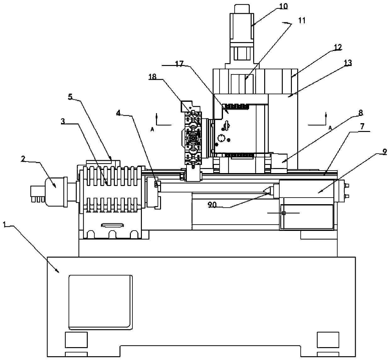
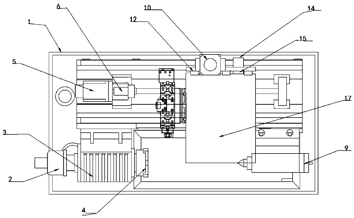
[0029] Such as Figure 1-2 As shown; a vertical rail type turning and milling compound machine tool of the present invention includes a machine base 1, a main shaft transmission device, a hydraulic tailstock 9, a Z-axis feed device, and...


PUM


Abstract

The invention relates to a vertical rail type turning and milling compound machine tool. The machine tool comprises a machine tool base, a main shaft transmission device, an oil pressure tail base, aZ-axle feeding device and an X-axle feeding device; the X-axle feeding device is fixedly arranged above a Z-axle slide table; a servo power machine shell is arranged on the X-axle feeding device, andis provided with a servo power machine head capable of moving in a Y direction; a tip is supported in a tip base through a composite bearing and double rows of conical roller bearings; a labyrinth sealing cover is arranged at one end of the tip, and forms a dynamic labyrinth sealing connection with the tip base; and a tail sealing cover is arranged at the other end of the tip, and is fixed with the tip base. The machine tool not only can realize turning and milling compound machining, but also can realize low weight of guide rails, and in particular, effectively improves the operability in theY direction; and a rotary tip module is supported by using the composite bearing, so that the structure is simple and compact, radial and axial loads can be borne at the same time, and the dynamic stability of the tip and the machining precision of the machine tool are greatly improved.

Description

technical field [0001] The invention belongs to the technical field of numerical control machine tools, and in particular relates to a vertical rail type turning and milling compound machine tool. Background technique [0002] The appearance of CNC lathes is similar to that of ordinary lathes, that is, it is composed of bed, spindle box, tool holder, feed, cooling system and lubrication system, etc., but the transmission system of CNC lathes has a qualitative leap from ordinary lathes. There are feed boxes and exchange gear racks, while CNC lathes directly use servo motors to drive through ball screws to achieve feed. [0003] Inventor Jiang Muyong has three prior applications, namely: a CNC machine tool with double spindles and turrets (CN205702457U), a vertical rail CNC lathe (CN202963464U), and a vertical rail CNC lathe (CN205816826U). Further improvements are made on the basis of the above contents. [0004] CNC lathes are generally equipped with a single tool holder, ...

Claims


Application Information

Patent Timeline
Patent Type & Authority Patents(China)
IPC IPC(8): B23P23/02B23B21/00B23B23/04B23B25/00
Inventor 蒋木勇
Owner 湖北山铁智能装备有限公司
Why Eureka
Try Eureka