Eureka AIR delivers breakthrough ideas for toughest innovation challenges, trusted by R&D personnel around the world.

Noise reduction structure for dry type transformer

A dry-type transformer, noise reduction technology, applied in transformer/inductor noise damping, transformer/inductor housing, transformer/inductor cooling, etc. Improves stability and avoids shocks

Inactive Publication Date: 2019-06-14
中科电力装备集团变压器有限公司
View PDF0 Cites 4 Cited by
  • Summary
  • Abstract
  • Description
  • Claims
  • Application Information

AI Technical Summary

Problems solved by technology

[0002] Dry-type transformers are widely used in places such as local lighting, high-rise buildings, airports, and wharf CNC machinery and equipment; simply speaking, dry-type transformers refer to transformers whose iron core and windings are not immersed in insulating oil; with the continuous advancement of urbanization in my country , Dry-type transformers are used more and more, and dry-type transformers are used to provide electric energy for high-rise residential quarters, office buildings, hospitals, hotels and other places; but when the dry-type transformer is running, its alternating magnetic field produces periodic alternating currents on the core and coil. The variable force causes its own vibration to the installed bottom plate, and the vibrating iron core coil radiates noise outward; under the action of the inner wire of the energized dry-type transformer and the spiral flow inside the iron core, the radiated noise is much higher than that of a single frequency The noise generated by vibration is more complex and disturbing to the people; the noise will not only affect the daily life of people in the building, but in serious cases will have a bad impact on people's health, and the same noise will also cause sound pollution, which is not conducive to people's health life

Method used


Image

  • Noise reduction structure for dry type transformer
  • Noise reduction structure for dry type transformer
  • Noise reduction structure for dry type transformer

Examples


Embodiment Construction

[0028] In order to make the object, technical solution and advantages of the present invention clearer, the present invention will be further described in detail below in combination with specific embodiments and with reference to the accompanying drawings. It should be understood that these descriptions are exemplary only, and are not intended to limit the scope of the present invention. Also, in the following description, descriptions of well-known structures and techniques are omitted to avoid unnecessarily obscuring the concept of the present invention.

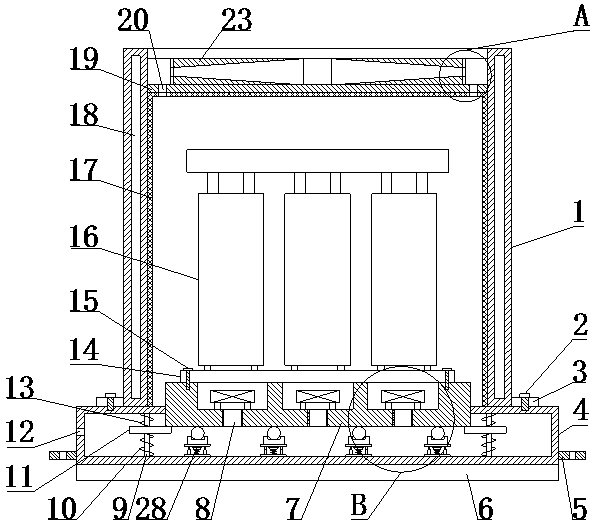
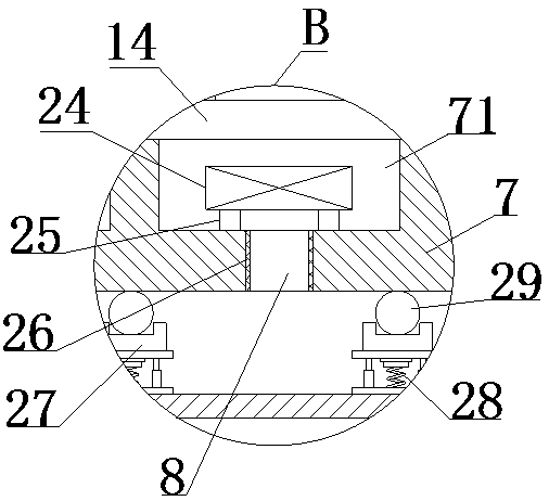
[0029] like Figure 1-5 As shown, a noise reduction structure for a dry-type transformer proposed by the present invention includes a housing 1, a first fastener 2, a first connecting plate 3, a base box 4 and a shock absorbing plate 6;

[0030] The lower end surface of the base box 4 is provided with a damping plate 6, the upper end surface of the base box 4 is provided with a second blind hole and a first opening, and ...


PUM


Abstract

A noise reduction structure for a dry type transformer comprises a casing, a first fastening member, first connecting plates, a base box and a shock absorbing plate, wherein the shock absorbing plateis arranged at the lower end surface of the base box, and a support table is arranged in a first opening of the base box; shock absorbing components arranged in the base box are respectively connectedto the support table and the base box; a second connecting plate is arranged on the support table, and the second connecting plate is slidably connected to a guide rod; a shock absorbing spring is sleeved outside the guide rod; mounting grooves are arranged on the upper end surface of the support table; second through holes are arranged at the bottoms of the mounting grooves; air blowing devicesare arranged in the mounting grooves; a first sound absorbing layer is respectively arranged on the inner wall of each second through hole; the first connecting plates are respectively arranged on thecasing, and the first connecting plates are connected to the base box through the first fastening member; a noise blocking piece is arranged on the inner wall of the casing, and a transformer is arranged in the casing; and the transformer is detachably connected to the support table. The noise reduction structure provided by the invention can effectively eliminate the noise generated by the operation of the dry type transformer, and can perform heat dissipation and cooling on the dry type transformer.

Description

technical field [0001] The invention relates to the technical field of noise reduction equipment, in particular to a noise reduction structure for dry-type transformers. Background technique [0002] Dry-type transformers are widely used in places such as local lighting, high-rise buildings, airports, wharf CNC machinery and equipment; simply speaking, dry-type transformers refer to transformers whose iron core and windings are not immersed in insulating oil; with the continuous advancement of urbanization in our country , Dry-type transformers are used more and more, and dry-type transformers are used to provide electric energy for high-rise residential quarters, office buildings, hospitals, hotels and other places; but when dry-type transformers are running, their alternating magnetic fields produce periodic alternating currents on the core and coils. The changing force causes itself to vibrate against the installed bottom plate, and the vibrating iron core coil radiates n...

Claims


Application Information

Patent Timeline
Patent Type & Authority Applications(China)
IPC IPC(8): H01F27/33H01F27/06H01F27/02H01F27/08F16F7/00
Inventor 王小飞杨坤生施洪华王丹
Owner 中科电力装备集团变压器有限公司
Why Eureka
Eureka Blog
Learn More