
Double-sided cathode spiral ring gradual change type silicon drift detector and preparation method thereof

A silicon drift detector and helical ring technology, applied in the field of radiation detection, can solve the problems of limited application of electric field distribution, large dead zone area, limited sensitivity of detector array, etc., to improve sensitivity and radiation resistance performance, reduce Dead zone area, the effect of increasing the effective detection area

Pending Publication Date: 2019-06-11
湖南正芯微电子探测器有限公司
View PDF0 Cites 1 Cited by
  • Summary
  • Abstract
  • Description
  • Claims
  • Application Information

AI Technical Summary

Problems solved by technology

[0005] The invention provides a double-sided cathode spiral ring gradient silicon drift detector and a preparation method thereof, which solves the problem that the existing single-sided circular spiral ring detector array has a relatively large dead area, which causes the sensitivity of the detector array to be limited and and The square spiral ring silicon drift detector cannot provide the best potential and electric field distribution near the detector N+ collecting anode, which limits its application

Method used


Image

  • Double-sided cathode spiral ring gradual change type silicon drift detector and preparation method thereof
  • Double-sided cathode spiral ring gradual change type silicon drift detector and preparation method thereof
  • Double-sided cathode spiral ring gradual change type silicon drift detector and preparation method thereof

Examples


Embodiment Construction

[0040] The following will clearly and completely describe the technical solutions in the embodiments of the present invention with reference to the accompanying drawings in the embodiments of the present invention. Obviously, the described embodiments are only some, not all, embodiments of the present invention. Based on the embodiments of the present invention, all other embodiments obtained by persons of ordinary skill in the art without making creative efforts belong to the protection scope of the present invention.

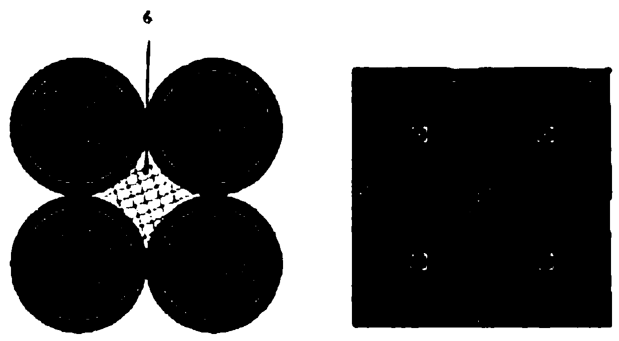
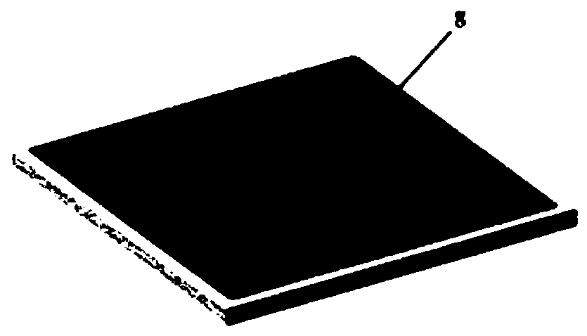
[0041] The double-sided cathode spiral ring gradient silicon drift detector, as shown in Figures 2 to 9, consists of the front surface of the gradient detector unit 7, the back surface of the gradient detector unit 8 and the high-resistance silicon substrate 14, and the front surface of the gradient detector unit 7 and the back side 8 of the gradual deformation detector unit are respectively located on two opposite planes of the high-resistance silicon substrat...


PUM

PropertyMeasurementUnit
Thicknessaaaaaaaaaa
Thicknessaaaaaaaaaa
Doping concentrationaaaaaaaaaa

Abstract

The invention discloses a double-sided cathode spiral ring gradual change type silicon drift detector and a preparation method thereof; the front surface of a gradual change type detector unit and theback surface of the gradual change type detector unit are positioned on two opposite planes of a high resistance silicon substrate; the front surface of the gradual change type detector unit comprises a first gradual change type P+ cathode spiral ring and an N+ collection anode embedded in the first gradual change type P+ cathode spiral ring, wherein the first gradual change type P+ cathode spiral ring is composed of a front circular region, a front gradual change region and a front square region; the back surface of the gradual change type detector unit comprises a second gradual change typeP+ cathode spiral ring, wherein the second gradual change type P+ cathode spiral ring is composed of a back circular area, a back surface gradual change region and a back surface square region; and amiddle electrode is arranged in the center of the second gradient type P+ cathode spiral ring. A silicon dioxide layer is generated on the surface of the N-type high-resistance silicon wafer througha gettering oxidation process, and the detector pattern is transferred to a silicon dioxide layer, and then etching and ion implantation and activation on each part are carried out; and finally the damage of the detector is repaired.

Description

technical field [0001] The invention belongs to the technical field of radiation detection, and relates to a double-sided cathode spiral ring gradient silicon drift detector and a preparation method thereof. Background technique [0002] Silicon Drift Detector (SDD) is developed for atomic physics, nuclear physics and elementary particle physics. Now, SDD is widely used in many fields such as science, engineering and daily life, such as deep space exploration, medical imaging, particle trajectory detection in high energy physics, food safety detection, and radiation source detection for national security. The SDD is a device used to detect trajectories and determine the energy of energetic particles. These high-energy particles include those produced by nuclear decay, cosmic radiation, and particles produced by accelerator interactions. To detect radiation, detectors must interact with matter and this interaction must be recorded. SDD is through the interaction between th...

Claims


Application Information

Patent Timeline
IPC IPC(8): H01L31/115H01L31/0352H01L31/18
CPCY02P70/50
Inventor 李正熊波
Owner 湖南正芯微电子探测器有限公司
Learn More