Wind turbine having an expanded voltage range

a wind turbine and voltage range technology, applied in the field of wind turbines, can solve the problems of insufficient infrastructure, voltage deviation, comparatively long switching time of these on-load tap changers, etc., and achieve the effects of increasing the voltage range of the wind turbine, reducing the complexity of the switching process, and reducing the number of switching cycles

Inactive Publication Date: 2016-10-20
SENVION GMBH
View PDF3 Cites 9 Cited by
  • Summary
  • Abstract
  • Description
  • Claims
  • Application Information

AI Technical Summary

Benefits of technology

[0005]On the basis of the mentioned prior art with the on-load tap changers, an object of the invention is to expand the voltage range of a wind turbine, wherein quicker switching times are intended to be achieved with little complexity.

Problems solved by technology

In many cases, these are areas with only insufficient infrastructure, which applies in particular to wind farms at sea (so-called offshore wind farms), at which there is generally no infrastructure at all yet.
Therefore, there are often voltage deviations in the case of wind farms with relatively high power feeds.
Therefore, although a comparatively large voltage range can be covered, the switching times of these on-load tap changers are comparatively long (up to in the minutes range), which is considered to be too slow.
In addition, the on-load tap changers are susceptible to wear.
However, this has the disadvantage that the semiconductor elements need to be dimensioned so as to be markedly large and are therefore elaborate since the total power is transmitted via said semiconductor elements.
For modern powerful wind turbines in the megawatts range, in practice this is barely possible.

Method used


Image

  • Wind turbine having an expanded voltage range
  • Wind turbine having an expanded voltage range
  • Wind turbine having an expanded voltage range

Examples


Embodiment Construction

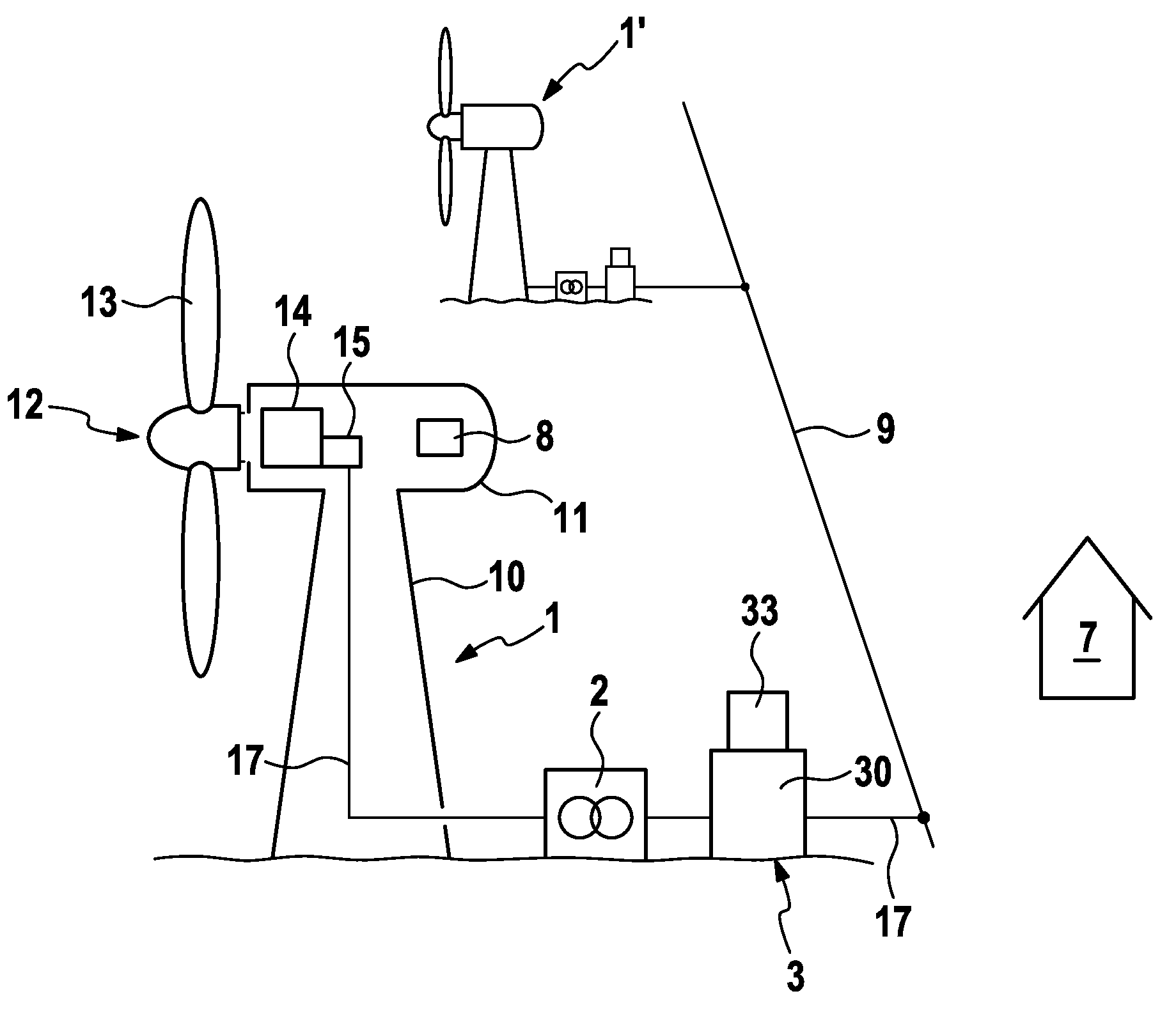
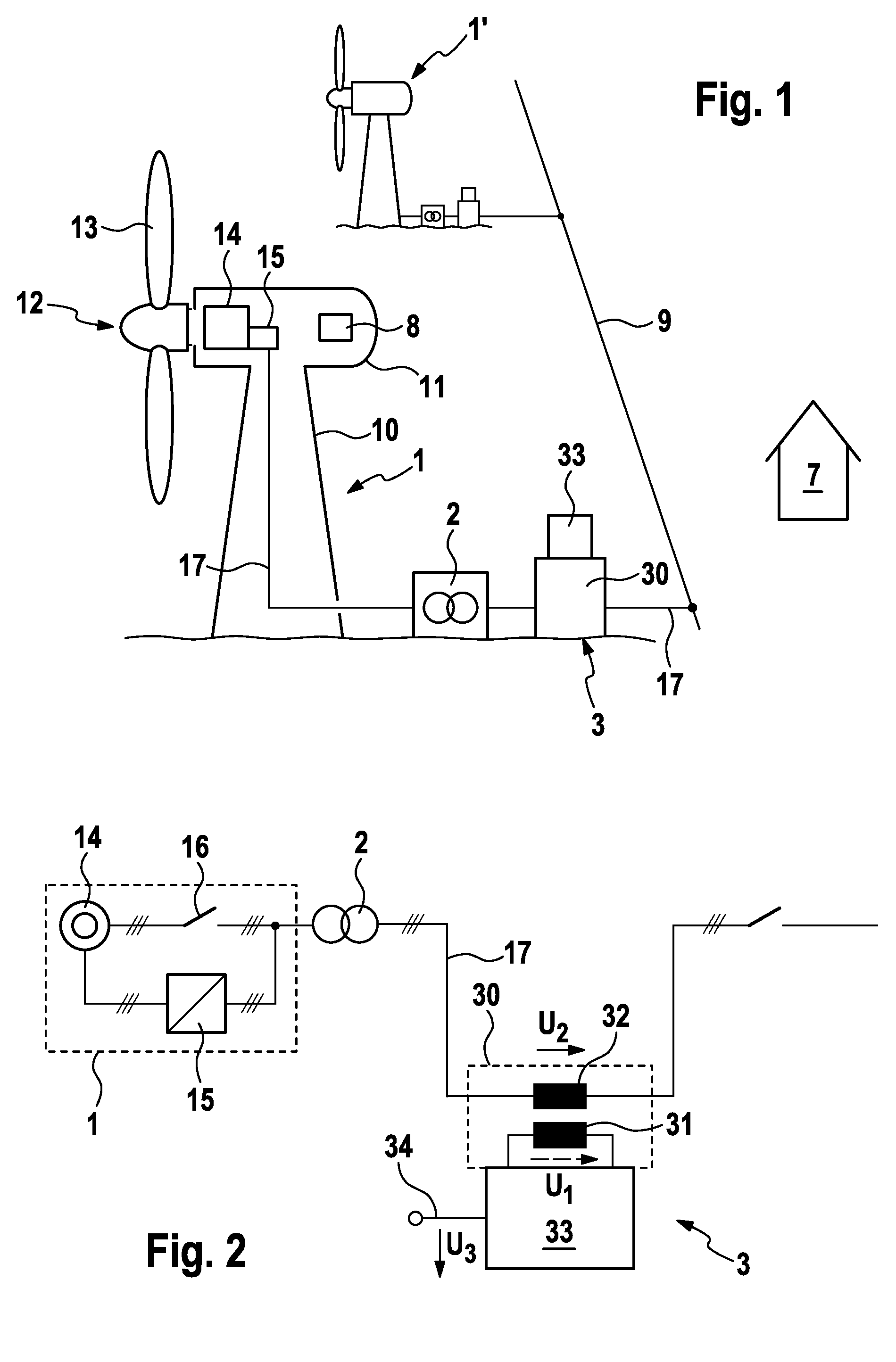
[0038]The wind turbine illustrated in FIG. 1 and provided overall with the reference numeral 1 comprises a nacelle 11 arranged on a tower 10 pivotably in the azimuthal direction at the upper end of the tower 10. The nacelle 11 has a rotatably mounted wind rotor 12 having rotor blades 13 on one of the end sides of said nacelle. Said wind rotor drives, via a shaft (not illustrated), a generator 14 comprising a converter 15 for generating electrical energy, which is output via a line 17 with a turbine transformer 2 of the wind turbine to a farm-internal grid. The operation of the wind turbine 1 is monitored by a control system 8, which is arranged in the nacelle 11. Said control system is connected to a farm master 7 and / or to superordinate control devices (not illustrated), in particular the grid operator, via communications lines (not illustrated).

[0039]The wind turbine 1 outputs the electrical energy on a low-voltage level, which is typically in the range of 600-1000 V. For the tran...


PUM


Abstract

A wind turbine having a wind rotor, a generator powered therewith for generating electrical energy, and a connecting line for delivering the electrical energy, optionally via a system transformer. The wind turbine includes a voltage expander that expands the voltage range of the wind turbine by means of an auxiliary voltage source. The voltage expander comprises a small transformer of having a primary and a secondary winding, and a switching mechanism. The small transformer is looped into the connecting line with the secondary winding, and the switching mechanism is connected to the primary winding of the small transformer, actuating the primary winding in a switchable multi-stage manner. Thus, a multi-stage expansion of the voltage range of the wind turbine is achieved, wherein due to the arrangement of the small transformer lengthwise in the connecting line, the small transformer can have a fraction of the nominal power of the wind turbine.

Description

REFERENCE TO RELATED APPLICATIONS[0001]This application is a national stage application under 35 USC 371 of International Application No. PCT / EP2014 / 055009, filed Mar. 13, 2014, which claims priority to German Application No. 10 2013 206 241.9, filed Apr. 9, 2013, the entire contents of which are incorporated herein by reference.FIELD OF THE INVENTION[0002]The invention relates to a wind turbine comprising a wind rotor, a generator driven thereby for generating electrical energy and a connecting line for outputting the electrical energy.BACKGROUND OF THE INVENTION[0003]As they are becoming increasingly widespread and at the same time their performance is increasing, wind farms are preferably erected at locations at which there good wind conditions, in particular on coastlines, at sea or in mountainous regions. In many cases, these are areas with only insufficient infrastructure, which applies in particular to wind farms at sea (so-called offshore wind farms), at which there is gener...

Claims


Application Information

Patent Timeline
Patent Type & Authority Applications(United States)
IPC IPC(8): H02J3/38H02J3/14H02J3/16
CPCH02J3/386H02J3/14H02J3/16H02J3/12H02J2300/28H02J3/381Y02E10/76Y04S20/222Y02B70/3225H02J3/44
Inventor LETAS, HEINZ-HERMANN
Owner SENVION GMBH
Why Eureka
Try Eureka