
Reliability test device of high-power laser chip

A technology of testing equipment and lasers, which is applied in the direction of electronic circuit testing, parts and instruments of electrical measuring instruments, etc., can solve problems such as difficult temperature control, high heat generation, and low testing efficiency, so as to ensure consistency and reduce differences , the effect of improving test efficiency

Pending Publication Date: 2019-06-11
STELIGHT INSTR CO LTD
View PDF0 Cites 3 Cited by
  • Summary
  • Abstract
  • Description
  • Claims
  • Application Information

AI Technical Summary

Problems solved by technology

[0003] The burn-in test can be used as a device reliability test or as a production window to find early failures of the device. Generally, the device used for chip burn-in test is to work together with the external circuit board through the test socket, and due to high-power lasers and chips, especially It is a laser and chip above 1W, which generates a lot of heat and is difficult to control temperature. Therefore, in the existing aging test equipment, most of them are operated by single measurement, resulting in low test efficiency

Method used


Image

  • Reliability test device of high-power laser chip
  • Reliability test device of high-power laser chip
  • Reliability test device of high-power laser chip

Examples


Embodiment 1

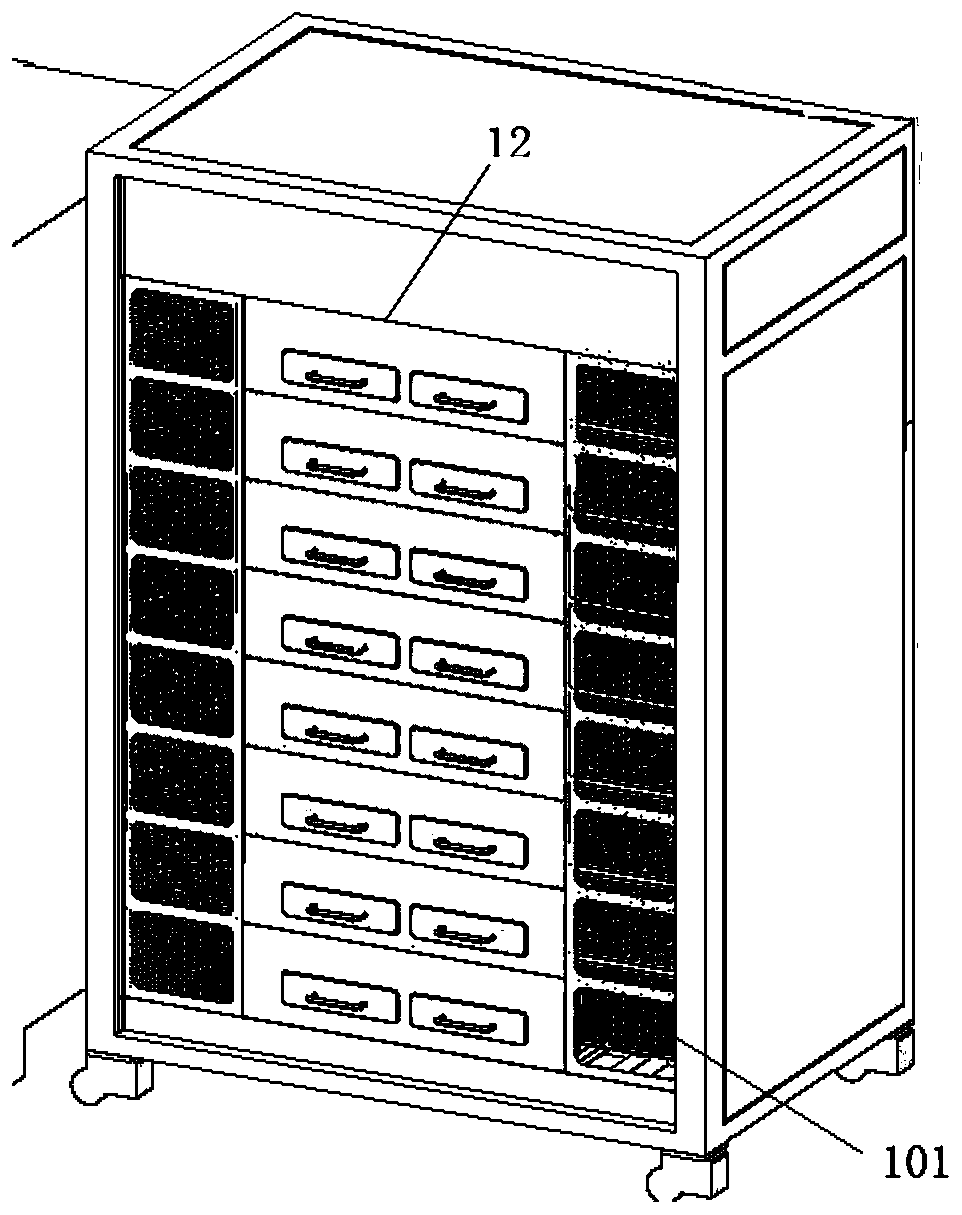
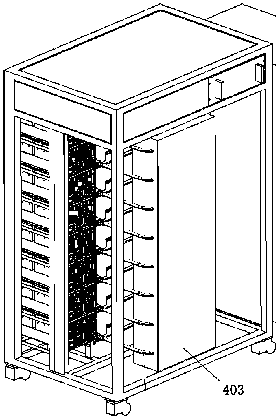
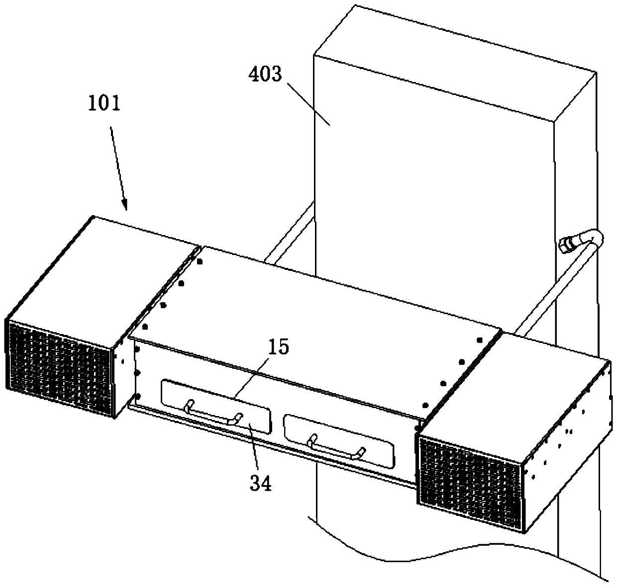
[0038] Embodiment 1: A kind of reliability test equipment of high-power laser chip, refer to attached Figure 1-9 , including a test carrier 1, a connection block 3 and a control assembly 101, the control assembly 101 includes a power supply module and a test module, the power supply module is used for chip power supply, and the test module is used for data collection and transmission of chip testing, A carrier board 2 is installed on the test platform 1, and a plurality of chip slots 201 for chip embedding are provided on the carrier board 2. There are several wires 21 connected to the chip on the carrier board 2, and these wires 21 are placed on the An electrical connector 22 is formed at one end of the carrier board 2, and a connection port 31 for inserting the power supply connector 22 is opened on the connection block 3, and the connection block 3 is electrically connected with the control assembly 101;

[0039] A cooling box 4 is arranged directly below the carrier plate...

Embodiment 2

[0046] Embodiment 2: a kind of reliability test equipment of high-power laser chip, refer to attached Figure 1-9 , including a test carrier 1, a connection block 3 and a control assembly 101, the control assembly 101 includes a power supply module and a test module, the power supply module is used for chip power supply, and the test module is used for data collection and transmission of chip testing, A carrier board 2 is installed on the test platform 1, and a plurality of chip slots 201 for chip embedding are provided on the carrier board 2. There are several wires 21 connected to the chip on the carrier board 2, and these wires 21 are placed on the An electrical connector 22 is formed at one end of the carrier board 2, and a connection port 31 for inserting the power supply connector 22 is opened on the connection block 3, and the connection block 3 is electrically connected with the control assembly 101;

[0047] A cooling box 4 is arranged directly below the carrier plate...


PUM


Abstract

The invention discloses a reliability test device of a high-power laser chip. A carrying plate comprises a plurality of chip grooves for embedding of chips; the carrying plate is provided with a plurality of wires communicated with the chips; the wires form an electric connector at one end of the carrying plate; a connecting block is provided with a connector for insertion of the electric connector; the connecting block is electrically connected with a control assembly; a cooling box including a water inlet and a water outlet is arranged under the carrying plate; a cooling cavity communicatedwith the water inlet and the water outlet is formed in the cooling box; the water inlet and the water outlet are communicated with a cooling water circulation box; and a heat conduction plate used forbeing in contact connection with the upper surface of the cooling box is also arranged at the lower surface of the carrying plate. While realizing batch testing of chips, the reliability test deviceof the high-power laser chip can take away heat generated by the chip test in real time, can efficiently control the chip test temperature, can prevent temperature influence fluctuation from affectingthe chip test precision and can greatly improve the chip test efficiency.

Description

technical field [0001] The invention relates to reliability testing equipment for high-power laser chips, belonging to the technical field of chip testing. Background technique [0002] Chip burn-in testing is an electrical stress testing method that uses voltage and high temperature to accelerate the electrical failure of a device, in which the burn-in process basically simulates running the entire life of the chip because the electrical stimulus applied during the burn-in process reflects the worst-case operation of the chip . [0003] The burn-in test can be used as a device reliability test or as a production window to find early failures of the device. Generally, the device used for chip burn-in test is to work together with the external circuit board through the test socket, and due to high-power lasers and chips, especially The lasers and chips above 1W generate a lot of heat and are difficult to control the temperature. Therefore, in the existing aging test equipmen...

Claims


Application Information

Patent Timeline
Patent Type & Authority Applications(China)
IPC IPC(8): G01R31/28G01R1/02G01R1/04
Inventor 罗跃浩徐鹏嵩赵山王化发
Owner STELIGHT INSTR CO LTD
Learn More