


Quick Research
Generate reliable direction feasibility study reports for your R&D in just a few steps.

Technical Q&A
Discover and master advanced knowledge NOW. Basics, ideas, possibilities, all at once.

Find Solutions
As an expert in R&D theories, this can generate solutions to your technical problems instantly.

Evaluate Feasibility
Analyze your overall solution with one click, know your potential R&D risks in advance.

Monitor Landscape
Get weekly tech updates, stay abreast of the latest tech innovations and key insights.
A high-power laser selective melting method for 3D printing high-speed rail brake discs
A laser selective melting and 3D printing technology, applied in the field of additive manufacturing, can solve problems such as deformation and cracking, achieve the effects of eliminating residual stress, good forming quality, and improving forming efficiency
- Summary
- Abstract
- Description
- Claims
- Application Information
AI Technical Summary
Problems solved by technology
Method used
Image

Examples
Embodiment 1
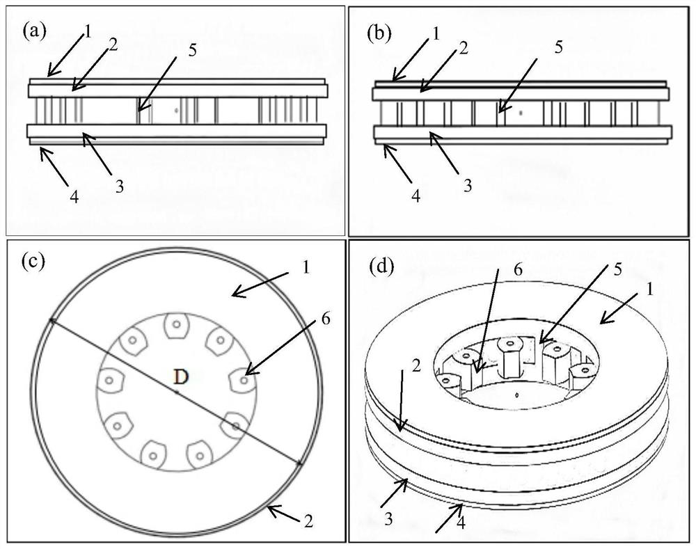
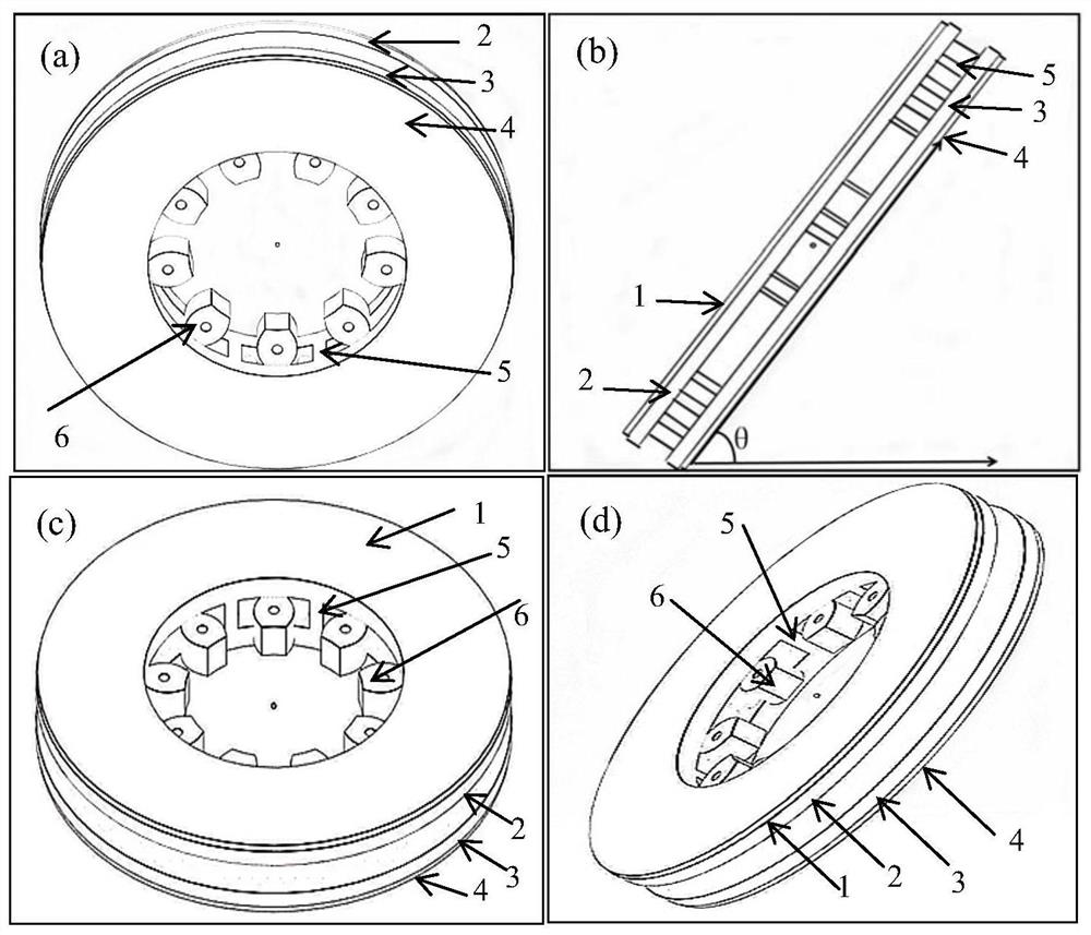
[0043] Import the designed brake disc model into the 3D printing software. The structure of the brake disc model is as follows: figure 1 As shown; set the diameter D of the brake disc model to 210mm, and then set the brake disc model to tilt, so that the angle between the upper and lower working surfaces of the brake disc model and the substrate is θ=45°, the structure is as follows figure 2 As shown; the brake disc model projection area is provided with a horizontal substrate model; the brake disc model is an axisymmetric structure, consisting of an annular upper part, an annular lower part, a reinforcing rib 5 and a plurality of assembly nuts connected to the reinforcing rib An integral structure composed of parts 6; the ring-shaped upper part is composed of the upper working panel 1 and the upper connecting plate 2 at the lower part; the top surface of the upper working panel 1 is called the upper working surface, and the side is called the side of the upper working surface...
Embodiment 2
[0057] Method is with embodiment 1, and difference is:
[0058] (1) The structure of the brake disc model is as follows: Figure 8 As shown; when the brake disc model is tilted, the angle between the upper and lower working surfaces and the base plate is θ=55°;
[0059] (2) When the top edge of the upper thin wall is connected to the side edge of the upper working surface, the outer edge of the top edge of the upper thin wall is connected to the upper edge of the side edge of the upper working surface, and the part where the upper thin wall is connected to the side edge of the upper working surface, It occupies 1 / 2 of the perimeter of the side of the upper working surface; when the top edge of the lower thin wall is connected with the side of the lower working surface, the outer edge of the top edge of the lower thin wall is connected with the lower edge of the side of the lower working surface, and the lower thin wall The part connected with the side of the lower working sur...
Embodiment 3
[0065] Method is with embodiment 1, and difference is:
[0066] (1) The structure of the brake disc model is as follows: Figure 10 As shown; when the brake disc model is tilted, the angle between the upper and lower working surfaces and the base plate is θ=50°;
[0067] (2) When the top edge of the upper thin wall is connected to the side edge of the upper working surface, the outer edge of the top edge of the upper thin wall is connected to the upper edge of the side edge of the upper working surface, and the part where the upper thin wall is connected to the side edge of the upper working surface, It occupies 1 / 2 of the perimeter of the side of the upper working surface; when the top edge of the lower thin wall is connected with the side of the lower working surface, the outer edge of the top edge of the lower thin wall is connected with the lower edge of the side of the lower working surface, and the lower thin wall The part connected with the side of the lower working su...
PUM
| Property | Measurement | Unit |
|---|---|---|
| thickness | aaaaa | aaaaa |
| tensile strength | aaaaa | aaaaa |
| diameter | aaaaa | aaaaa |
Abstract
Description
Claims
Application Information
 - R&D Engineer
- R&D Manager
- IP Professional
- Industry Leading Data Capabilities
- Powerful AI technology
- Patent DNA Extraction
Browse by: Latest US Patents, China's latest patents, Technical Efficacy Thesaurus, Application Domain, Technology Topic, Popular Technical Reports.
© 2024 PatSnap. All rights reserved.Legal|Privacy policy|Modern Slavery Act Transparency Statement|Sitemap|About US| Contact US: help@patsnap.com