Engine
An engine and cylinder technology, applied in the field of engines, can solve the problems of low energy conversion rate of internal combustion engines and external combustion engines, achieve the effect of increasing the contact area, increasing the degree of air turbulence, and improving the overall performance
- Summary
- Abstract
- Description
- Claims
- Application Information
AI Technical Summary
Problems solved by technology
Method used
Image

Examples
Embodiment 1
[0075] One end of the Stirling engine is a hot chamber and the other end is a cold chamber. Under the action of different temperatures, it performs periodic compression and expansion in a closed cycle. The gasoline engine forms a reciprocating work through the four strokes of intake, compression, power and exhaust. Combining the Stirling engine and the gasoline engine forms a two-stage power conversion, which greatly improves the power conversion rate of the gasoline engine.
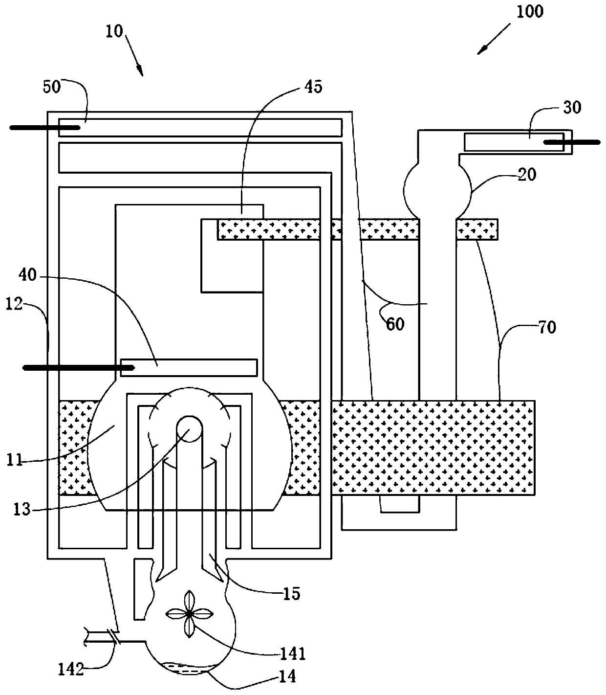
[0076] Please also refer to figure 1 and figure 2 , the engine 100 includes a heating chamber 10 , a cold air buffer chamber 20 and a cold cylinder 30 . The cold air buffer chamber 20 is provided with a cold air cylinder 30 , and the cold air cylinder 30 communicates with the cold air buffer chamber 20 . The cold air cylinder 30 includes a cylinder body 31 and a piston 32 , a piston rod 33 is connected to the piston 32 , and the piston 32 slides in the cylinder body 31 . The rod chamber of the cylin...
Embodiment 2
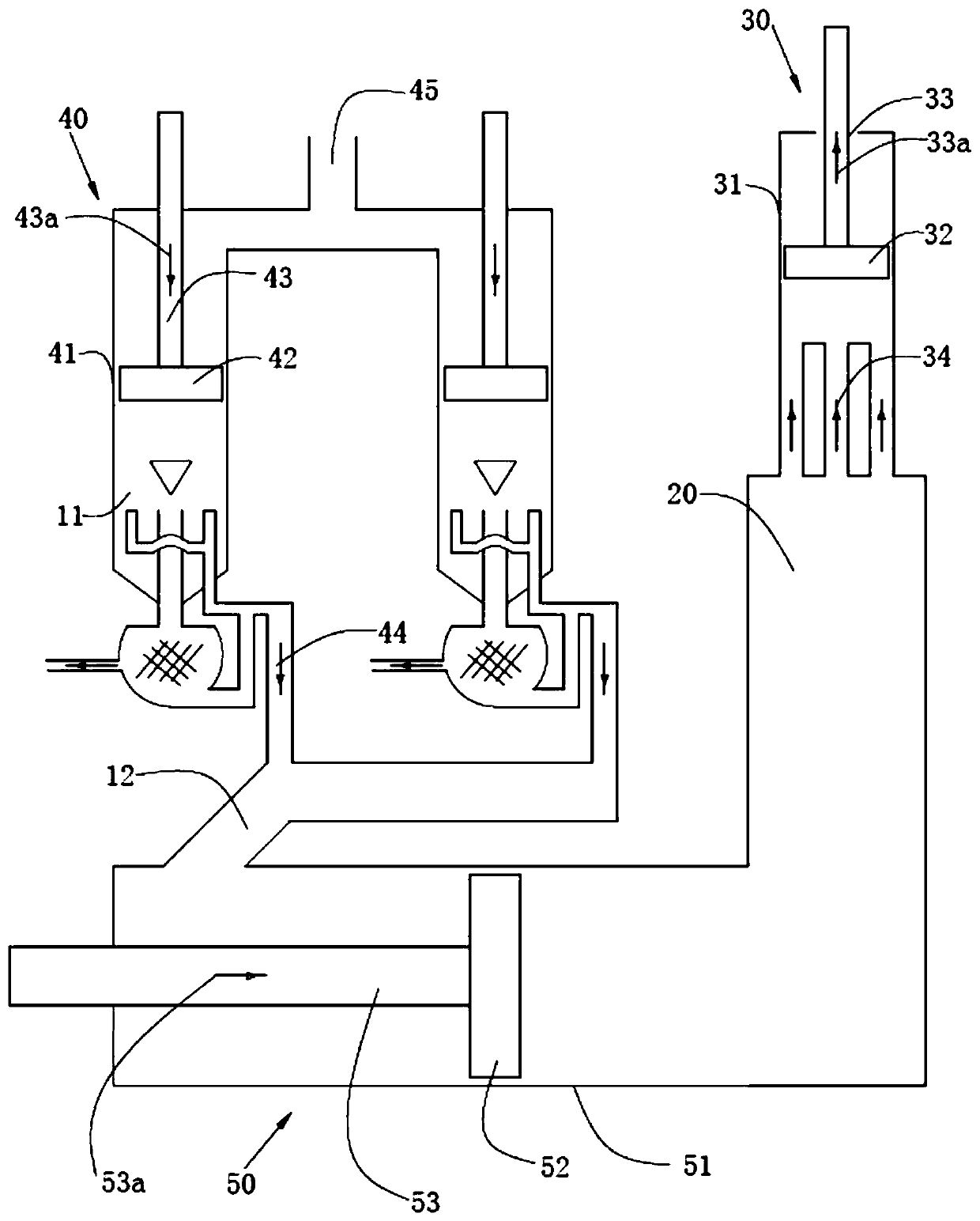
[0095] Figure 4 A schematic structural diagram of an engine 200 provided by the second embodiment of this embodiment is shown.
[0096] Please also refer to figure 2 , the engine 200 includes a heating chamber 80 , a cold air buffer chamber 20 and a cold cylinder 30 . The cold air buffer chamber 20 is provided with a cold air cylinder 30 , and the cold air cylinder 30 communicates with the cold air buffer chamber 20 . The cold air cylinder 30 includes a cylinder body 31 and a piston 32 , a piston rod 33 is connected to the piston 32 , and the piston 32 slides in the cylinder body 31 . The rod chamber of the cylinder body 31 takes in air, and the rodless chamber communicates with the cold air buffer chamber 20 .
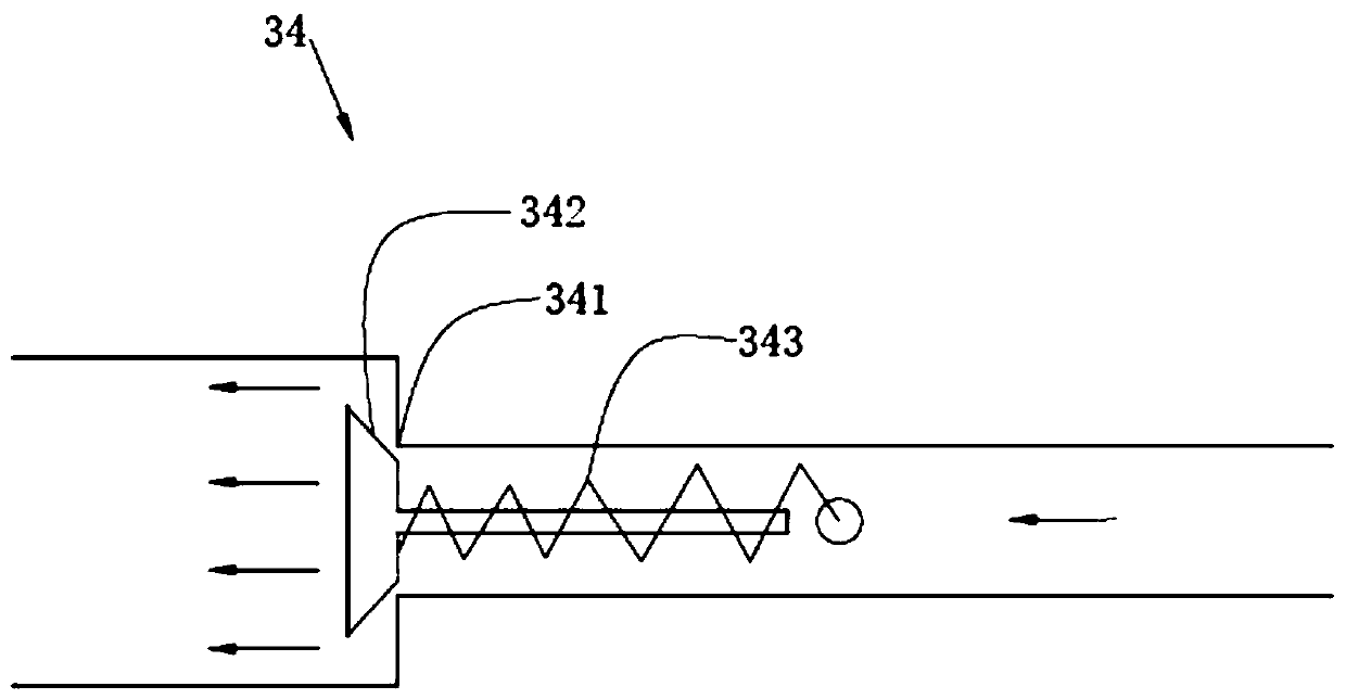
[0097] A first one-way air guide device 34 is provided between the cold cylinder 30 and the preheated cylinder 50 mentioned below, and the cold cylinder 30 is air-intaked. Such as image 3 As shown, the first one-way air guiding device 34 includes a valve 341 ,...
Embodiment 3
[0121] A kind of engine, the difference with embodiment 2 is, as Figure 5 As shown, the heat conduction device 90 includes a heat dissipation pipe 91, a heat sink 92, a fixed plate 93 and a heat conduction block 94, the fixed plate 93 is fixedly connected with the outer wall of the cold air buffer chamber 20, the heat dissipation pipe 91 is fixedly connected with the fixed plate 93, and the heat sink 92 Fixedly connected with the heat dissipation pipe 91, the cold air buffer chamber 20 conducts heat to the fixed plate 93 and the heat dissipation pipe 91, and the heat dissipation pipe 91 conducts the heat to the heat dissipation fin 92, and the heat dissipation fin 92 increases the distance between the heat dissipation pipe 91 and the outside air. The contact area increases the heat dissipation rate.
[0122] The cooling fins 92, the cooling pipes 91 and the fixing plate 93 are all made of wrought iron or aluminum, and have good flexibility, plasticity and ductility. The outer...
PUM
 Abstract
Description
Claims
Application Information
 - R&D
- Intellectual Property
- Life Sciences
- Materials
- Tech Scout
- Unparalleled Data Quality
- Higher Quality Content
- 60% Fewer Hallucinations
Browse by: Latest US Patents, China's latest patents, Technical Efficacy Thesaurus, Application Domain, Technology Topic, Popular Technical Reports.
© 2025 PatSnap. All rights reserved.Legal|Privacy policy|Modern Slavery Act Transparency Statement|Sitemap|About US| Contact US: help@patsnap.com