SAW (surface acoustic wave) gyroscope based on standing wave mode

A gyroscope and mode technology, which is applied in the computer field, can solve the problems affecting the sensitivity of the device, the sensitivity does not meet the actual needs, and the signal changes are weak, so as to achieve the effect of improving the accuracy and sensitivity

Active Publication Date: 2019-05-21
ZHONGBEI UNIV
View PDF7 Cites 6 Cited by
  • Summary
  • Abstract
  • Description
  • Claims
  • Application Information

AI Technical Summary

Problems solved by technology

[0004] The output signal of the standing wave mode SAW gyroscope is a microvolt-level electrical signal, and the measurement error range is large; the substrate is made of LiNbO 3 , although it has a high electromechanical coupling coefficient, but the large temperature coefficient will affect the instability of the device
Although the traveling wave mode SAW gyroscope uses a differential structure to achieve temperature compensation, because the Coriolis force directly affects the sound wave velocity, the quality of the metal lattice affects the sensitivity of the device. The sensitivity of the small mass does not meet the actual needs, and the large mass affects the sound wave propagation and increases the design cost. , the frequency change is also very small
Both modes have the problems of weak signal changes and complex circuits of the transceiver module, which will increase the formation of errors, the size of the device will also become larger, and the matching problem needs to be solved during the design process

Method used


Image

  • SAW (surface acoustic wave) gyroscope based on standing wave mode
  • SAW (surface acoustic wave) gyroscope based on standing wave mode
  • SAW (surface acoustic wave) gyroscope based on standing wave mode

Examples


Embodiment Construction

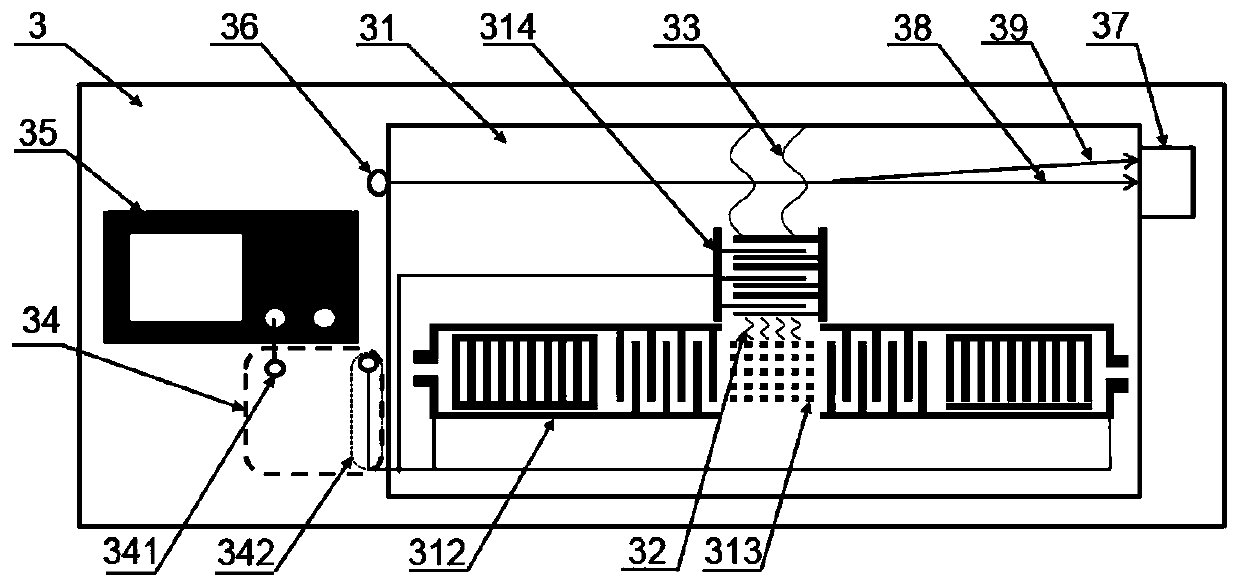
[0070] For a more comprehensive understanding of the standing wave mode-based SAW gyroscope of the present application, the present application will be further described in detail below in conjunction with the accompanying drawings.

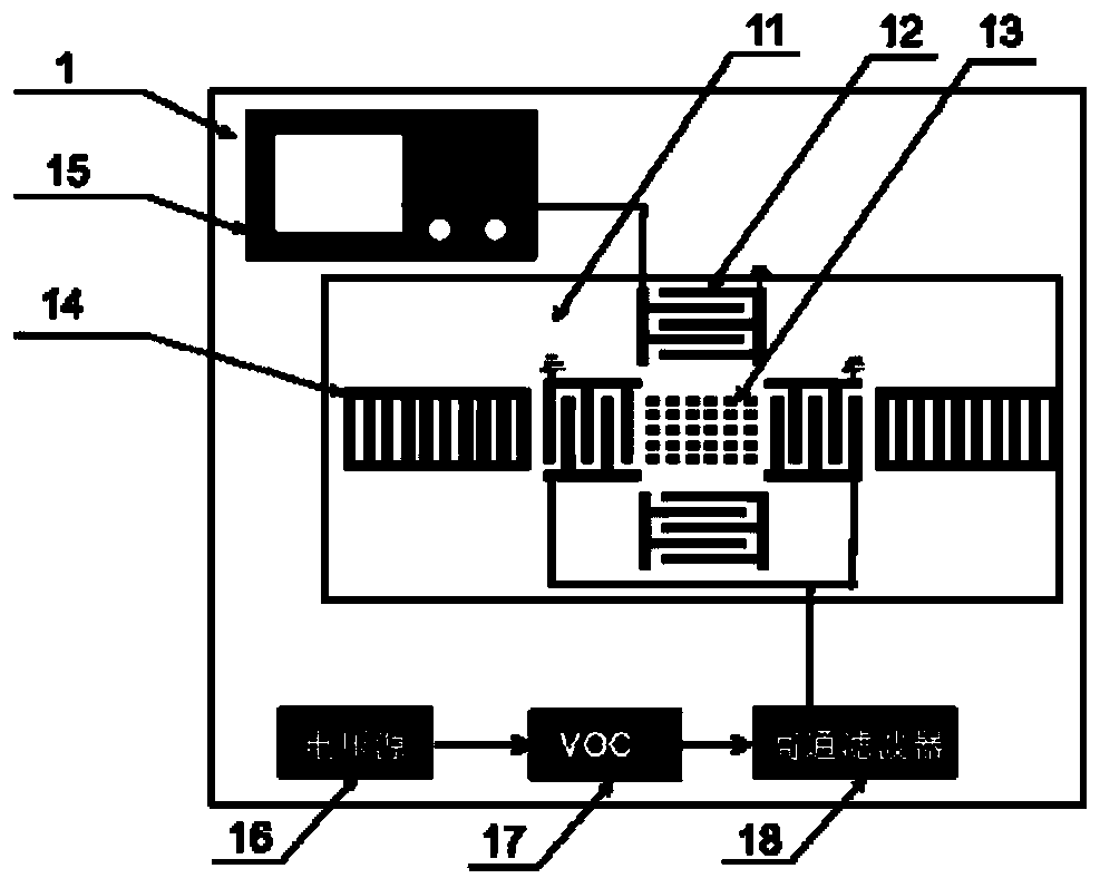
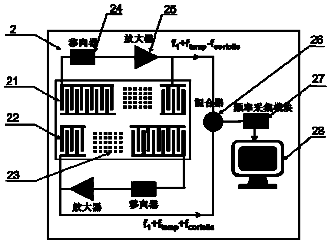
[0071] like image 3 As shown, a surface acoustic wave (SurfaceAcoustic Wave, SAW) gyroscope based on a standing wave mode in an embodiment of the present application, the SAW gyroscope (3) includes a transceiver antenna (34), a piezoelectric substrate (31) , a two-port resonator (312) and a SAW receiving end (314) placed on the surface of the piezoelectric substrate (31), and a metal lattice (313) distributed in the resonant cavity of the two-port resonator (312) ); the two-port resonator (312) includes two symmetrically arranged interdigital transducers (3122), and the metal lattice (313) is distributed between the two interdigital transducers (3122) ), a reflection grid (3123) is arranged on the outside of each of the interdigital transducers...


PUM

PropertyMeasurementUnit
Thicknessaaaaaaaaaa

Abstract

The invention aims to provide an SAW (surface acoustic wave) gyroscope based on a standing wave mode. According to the SAW gyroscope based on the standing wave mode, a 128-degree Y-X cut LiNbO3 piezoelectric substrate with the high piezoelectric coupling coefficient, high SAW propagation speed and large acoustic-optical coupling coefficient is adopted; a metal dot matrix made of gold and an SAW receiving end in an acousto-optic reading mode are placed between resonant cavities of a dual-port resonator triggered by a receiving and transmitting antenna, so that a novel gyroscope in a standing wave mode is realized. Due to the design of the receiving and transmitting antenna, electronic circuit modules required by the SAW gyroscope can be effectively reduced, that is, the use of external circuits is reduced; and the SAW receiving end adopts a high-precision acousto-optic coupling mode to read out the change of the angular rate, so that the accuracy and the sensitivity of the SAW gyroscopeare improved.

Description

technical field [0001] The present application relates to the field of computers, in particular to a SAW gyroscope based on a standing wave mode. Background technique [0002] Gyroscopes have great application requirements in consumer products, industrial and medical products, especially in the military field, and performance parameters determine the field of use. Currently there are fiber optic gyroscopes, laser gyroscopes and micro-electro-mechanical system (Micro-Electro-Mechanical System, MEMS) gyroscopes. SAW gyroscopes have significant advantages such as small size, low cost, high two-dimensional structural stability, easy mass production, high sensitivity, and strong anti-vibration ability, and have a wider range of applications. [0003] At present, there are mainly two types of surface acoustic wave (Surface Acoustic Wave, SAW) gyroscopes: standing wave mode and traveling wave mode. The SAW gyroscope based on the standing wave mode consists of a piezoelectric subs...

Claims


Application Information

Patent Timeline
IPC IPC(8): G01C19/5698
Inventor 耿文平丑修建陈茜乔骁骏穆继亮何剑侯晓娟
Owner ZHONGBEI UNIV
Why Eureka
Try Eureka