
Cooling system and method of computer room

A cooling system and equipment room technology, applied in the direction of cooling/ventilation/heating transformation, can solve the problems of increasing data center energy consumption, unsatisfactory cooling effect, and cooling equipment failure, so as to improve heat exchange efficiency and improve energy resource utilization. , the effect of less moving parts

Active Publication Date: 2019-05-14
南京艾科美热能科技有限公司
View PDF7 Cites 8 Cited by
  • Summary
  • Abstract
  • Description
  • Claims
  • Application Information

AI Technical Summary

Problems solved by technology

[0003] At present, traditional thermal management technologies, such as air forced convection cooling, single-phase liquid cooling, etc., often have problems with unsatisfactory heat dissipation due to factors such as insufficient heat transfer capacity or restricted by conditions.
At the same time, since the computer room system of the data center is basically in a state of uninterrupted operation, traditional cooling equipment needs to keep running to prevent the temperature of the computer room system from exceeding the standard, which not only increases the energy consumption of the data center, but is also prone to failure of the cooling equipment due to long-term operation The problem
In addition, although there are a variety of heat dissipation methods, in most cases the heat dissipation system only uses one or two of them, and the heat dissipation method is relatively simple, ignoring the changes in the basic heat load of the heat dissipation system caused by the outdoor ambient temperature changing with the seasons. As well as the dynamic load change of the cooling system caused by the outdoor ambient temperature changing with time during the day, it is easy to cause energy waste. Therefore, there is a need for multiple cold sources to work together and operate flexibly to achieve high-efficiency and low-energy cooling of the computer room system.

Method used


Image

  • Cooling system and method of computer room
  • Cooling system and method of computer room
  • Cooling system and method of computer room

Examples


Embodiment Construction

[0051] The accompanying drawings in the following description introduce preferred embodiments of the present invention to make the technical content clearer and easier to understand. The present invention can be embodied in many different forms of embodiments, and the protection scope of the present invention is not limited to the embodiments mentioned herein.

[0052] A further detailed description is carried out below in conjunction with the description of the accompanying drawings:

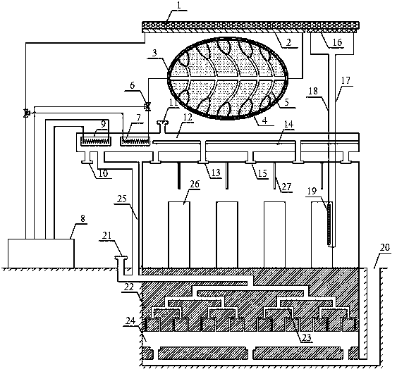
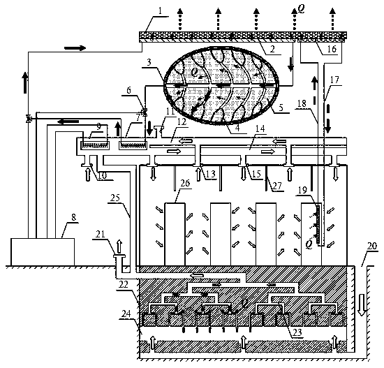
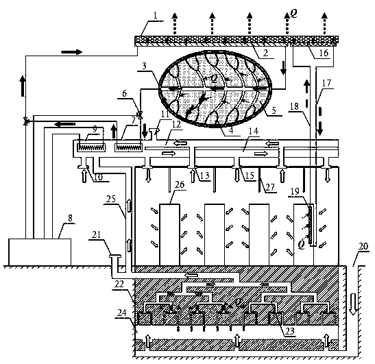
[0053] figure 1 Shown is a structural diagram of an integrated cooling system for a machine room, which is a composite self-cooling heat dissipation system composed of a radiation refrigeration device, a self-driven gas-liquid phase change heat transfer device, an underground cold storage device, a supplementary cooling device, and a ventilation system. in,

[0054] The radiant refrigeration device includes a radiant refrigeration plate 1, a circulating water cooling plate 2, a cold storage b...


PUM


Abstract

The invention discloses a cooling system of a computer room. The cooling system comprises a radiation refrigeration device, a self-driving gas-liquid phase-change heat transfer device, an undergroundcold storage device, a cold-supplementing device and a ventilation system. Multi-cold-source cooling is provided for a computer room heat dissipation system through the radiation refrigeration device,the self-driving gas-liquid phase-change heat transfer device, the underground cold storage device and the cold-supplementing device. The cooling system combines a self-driving phase-change heat transfer technology, a deep space radiation refrigeration technology and a phase-change energy storage technology to conduct scientific integrated optimal design on the heat dissipation system of the all-weather operation data center computer room, according to dynamic change of the external environment and the heat load, coordinative work between all cold sources is realized, under the premise of ensuring good heat dissipation of the whole system, energy and resource consumption can be saved to the maximum extent, and safe and stable operation of equipment can be ensured.

Description

technical field [0001] The invention relates to a computer room cooling integrated system with energy-saving and environment-friendly features designed to realize high-efficiency heat dissipation in computer rooms, data centers, etc., and belongs to the field of heat dissipation and energy-saving systems. Background technique [0002] With the rapid rise and vigorous development of big data and artificial intelligence industries, the data center computer room, as a space carrier supporting cloud computing services, is bound to develop in the direction of high power consumption and high integration. The sharp increase in heat flux makes the computer room The heat dissipation and energy consumption of the system are getting more and more attention. At present, my country is facing the contradiction between rapid economic growth and insufficient carrying capacity of environmental resources. Energy conservation and environmental protection have become the themes of development a...

Claims


Application Information

Patent Timeline
IPC IPC(8): H05K7/20
Inventor 徐德好
Owner 南京艾科美热能科技有限公司
Learn More