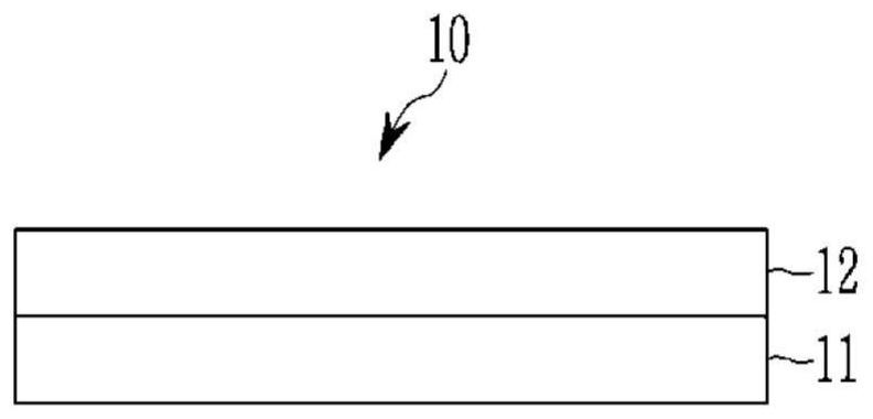
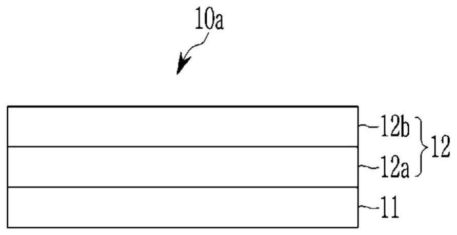
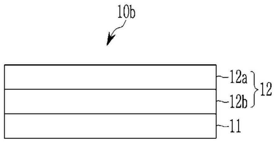
Optical filter, camera module and electronic device including same
A technology of optical filters and organic dyes, applied in the fields of optical filters, cameras, chemical instruments and methods for photographic purposes, can solve the problem of less filters, and achieve the effect of reducing optical distortion
Active Publication Date: 2022-05-31
SAMSUNG ELECTRONICS CO LTD
View PDF17 Cites 0 Cited by
- Summary
- Abstract
- Description
- Claims
- Application Information
AI Technical Summary
Problems solved by technology
[0008] The above plastic substrate may contribute little to thinning the filter, but causes a glare phenomenon in which when an object with high brightness is observed or imaged, a border around the object is seen (wifi type glare phenomenon) , light spreading or flickering around the object (petal glare phenomenon), etc.
Method used
View moreImage
Smart ImageViewing Examples
Examples
Embodiment 1
[0261] The first near-infrared absorption layer is formed by mixing a THF solvent and copper phosphoric acid represented by Chemical Formula 4a
Embodiment 2
Embodiment 3
Login to View More PUM
| Property | Measurement | Unit |
|---|---|---|
| thickness | aaaaa | aaaaa |
| thickness | aaaaa | aaaaa |
| thickness | aaaaa | aaaaa |
Abstract
Optical filters, and camera modules and electronic devices including the same are disclosed. The filter includes a near infrared absorbing layer on a polymer film. The polymer film has an a* of about -5.0 to about +5.0 and a b* of about -5.0 to about +5.0 in color coordinates expressed by the CIE Lab color space. The near-infrared absorbing layer may be configured to transmit light in a visible region and selectively absorb at least a portion of light in a near-infrared region. The near-infrared absorbing layer includes a first near-infrared absorbing material including a copper phosphate compound and a second near-infrared absorbing material including at least two different organic dyes. The second near-infrared absorbing material has a maximum absorption wavelength (λ 最大 ).
Description
Optical filter, and camera module and electronic device including the same CROSS-REFERENCE TO RELATED APPLICATIONS [0002] This application requires Korean Patent Application No. 10- filed at the Korean Intellectual Property Office on November 1, 2017 2017‑0144897, the entire contents of which are hereby incorporated by reference. technical field [0003] An optical filter (optical filter) and a camera module and electronic device including the same are disclosed. Background technique [0004] Recently, electronic equipment such as a hand including an image sensor that stores an image as an electrical signal has been widely used computer, digital camera, camcorder (camcorder) and camera (camera). [0005] The electronic device may include a filter having near-infrared absorption capabilities to reduce or prevent Generation of optical distortion (distortion) caused by light in the region of the visible light region. [0006] This filter is typically mounted in front of t...
Claims
Login to View More Application Information
Patent Timeline
 Patent Type & Authority Patents(China)
IPC IPC(8): G02B5/22G03B11/00G03B30/00
CPCG02B5/223G02B5/208G02B1/04G02B1/11C08K5/0041C08K5/3417C08K5/29C08K5/521C08J7/04C08K2003/085C08K5/52C08K3/08C08K5/235C09B23/08C09B57/007C09B57/00C09B53/02H10K30/80H10K39/32
Inventor 元钟勋金畅基金炯俊李龙柱郑明燮
Owner SAMSUNG ELECTRONICS CO LTD
Features
- R&D
- Intellectual Property
- Life Sciences
- Materials
- Tech Scout
- Unparalleled Data Quality
- Higher Quality Content
- 60% Fewer Hallucinations
Learn More Browse by: Latest US Patents, China's latest patents, Technical Efficacy Thesaurus, Application Domain, Technology Topic, Popular Technical Reports.
© 2025 PatSnap. All rights reserved.Legal|Privacy policy|Modern Slavery Act Transparency Statement|Sitemap|About US| Contact US: help@patsnap.com


