Movable bench drill with detection function

A bench drilling and functional technology, applied in the direction of measuring/indicating equipment, large fixed members, maintenance and safety accessories, etc., can solve the problems of difficult coolant collection, easy generation of debris, waste of resources, etc., to achieve convenient and intuitive detection, increase Stable and easy to move

Active Publication Date: 2019-05-07
山东金增精密机械有限公司
View PDF6 Cites 3 Cited by
  • Summary
  • Abstract
  • Description
  • Claims
  • Application Information

AI Technical Summary

Problems solved by technology

[0003] The existing bench drills are generally inconvenient to move, and it is inconvenient to perform drilling operations on workpieces in different positions in the workshop. At the same time, when the existing bench drills are drilling, it is not easy to visually detect the quality of the drill bit during the drilling process. , which will affect the drilling accuracy of the drill bit. In the process of drilling the workpiece, the surface is prone to debris, and the existing ones are not easy to clean the debris during the processing of the workpiece, which will make the debris It hinders the drill bit, affects the precise drilling of the drill bit, and it is not easy to collect the used coolant, which causes a waste of resources. Therefore, it is necessary to design a movable bench drill with a detection function to solve the current problem. There are technical deficiencies

Method used


Image

  • Movable bench drill with detection function
  • Movable bench drill with detection function
  • Movable bench drill with detection function

Examples


Embodiment Construction

[0022] The following will clearly and completely describe the technical solutions in the embodiments of the present invention with reference to the accompanying drawings in the embodiments of the present invention. Obviously, the described embodiments are only some, not all, embodiments of the present invention. Based on the embodiments of the present invention, all other embodiments obtained by persons of ordinary skill in the art without making creative efforts belong to the protection scope of the present invention.

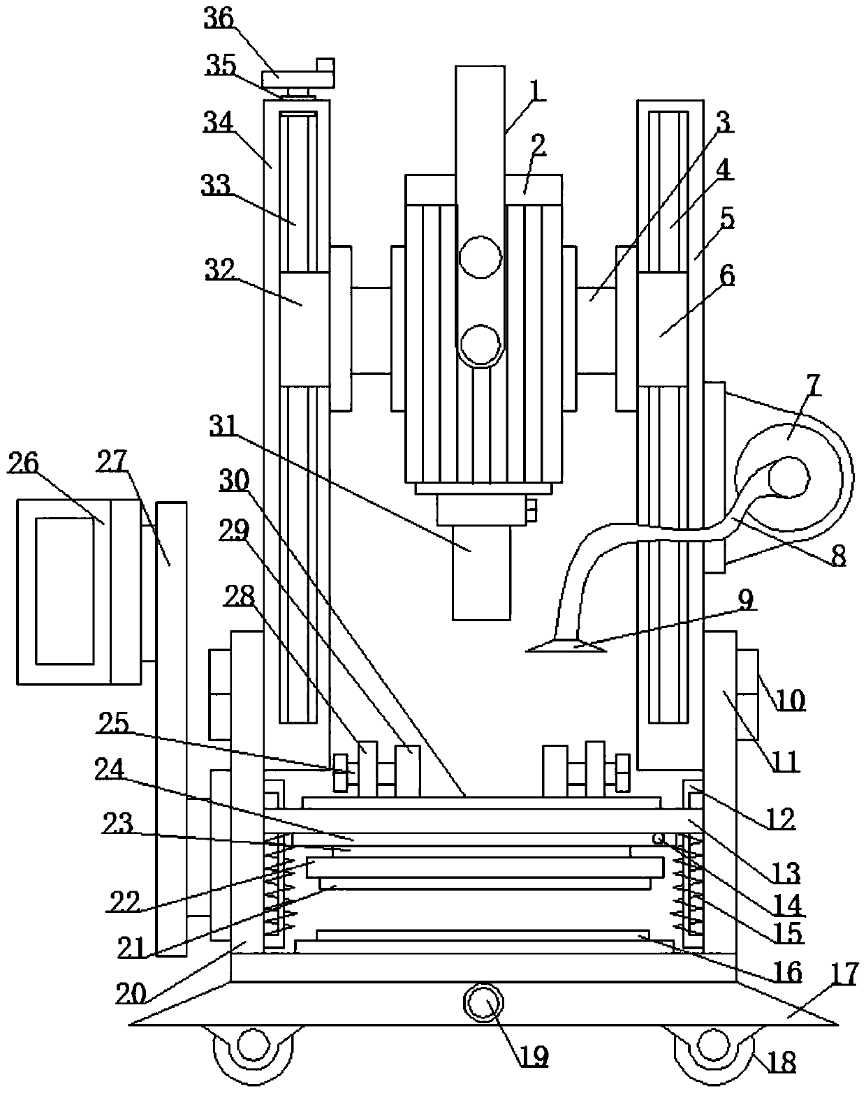
[0023] see Figure 1-4 , the present invention provides a technical solution:

[0024] A movable bench drill with a detection function, comprising a base 17 and a motor 2, the bottom surface of the base 17 is evenly equipped with a roller device 18, the side of the base 17 is fixedly equipped with a warning light 19, and the upper surface of the base 17 is The middle part is fixed with the first contact plate 16, and the left and right sides of the upper surf...


PUM

PropertyMeasurementUnit
Stiffness coefficientaaaaaaaaaa

Abstract

The invention aims to solve the problems that an existing bench drill is inconvenient to move and a drill bit cannot be detected in the working process, and discloses a movable bench drill with a detection function. The bench drill comprises a pulling rod, a motor, a connecting rod, a guide rod, a first guide frame, a first sleeve, a draught fan, a guide pipe, an air outlet head, a fastening screw, a first connecting plate, a second guide frame, a sliding plate, a liquid outlet, a spiral spring, a first contact plate, a base, a roller device, a warning lamp, a second connecting plate, a secondcontact plate, a mounting plate, a positioning ring, a clamping plate, a filter plate, a drill bit, a second sleeve, a feeding shaft, a main shaft frame, a connecting ring and a turntable. Accordingto the bench drill, through the first contact plate, the second contact plate, and the warning lamp, the strength of drilling on a workpiece can be detected in real time, and if the workpiece is drilled only when the strength is large, it proves that the drill bit is not sharp, and the resistance is large; and if the workpiece can be drilled when the strength is not large, it proves that the drillbit is sharp, so that the sharpness degree of the drill bit can be rapidly detected.

Description

technical field [0001] The invention relates to the field of bench drills, in particular to a movable bench drill with a detection function. Background technique [0002] The desktop drilling machine can be placed on the workbench, and the spindle is a small drilling machine arranged vertically. The spindle box and workbench of the vertical drilling machine are placed on the column, and the spindle is arranged vertically. The radial drilling machine can rotate and lift around the column, and usually the headstock can move horizontally on the rocker. The workbench of the milling and drilling machine can move vertically and horizontally, and the drilling axis is arranged vertically. It is a drilling machine capable of milling. The deep hole drilling machine uses a special deep hole drill bit, and the workpiece is rotated to drill a deep hole. Flat end face center hole drilling machine cutting shaft end face and center hole drilling machine processed with center drill. The ...

Claims


Application Information

Patent Timeline
IPC IPC(8): B23Q17/09B23Q17/00B23Q1/01B23Q11/00
Inventor 姜友松
Owner 山东金增精密机械有限公司
Why Eureka
Try Eureka