Method and device in user equipment and base station used for wireless communication
一种无线通信、用户设备的技术,应用在支持寻呼相关信息传输领域
- Summary
- Abstract
- Description
- Claims
- Application Information
AI Technical Summary
Problems solved by technology
Method used
Image


Examples
Embodiment 1
[0080] Embodiment 1 illustrates the flowchart of the transmission of the first information, the first sequence and the first wireless signal according to an embodiment of the present application, as shown in the attached figure 1 shown. attached figure 1 In , each box represents a step. In Embodiment 1, the user equipment in this application first receives the first information, then detects the first sequence in the target air interface resource, and then receives the first wireless signal if the first sequence is detected; wherein, the target The air interface resource is one of M candidate air interface resources, the first sequence is repeatedly sent Q times in the time domain resources included in the target air interface resource, the M is related to the Q, and the first The information is used to determine the time domain resources included in the target air interface resources, and the M and the Q are positive integers respectively.
[0081] As an embodiment, if the...
Embodiment 2
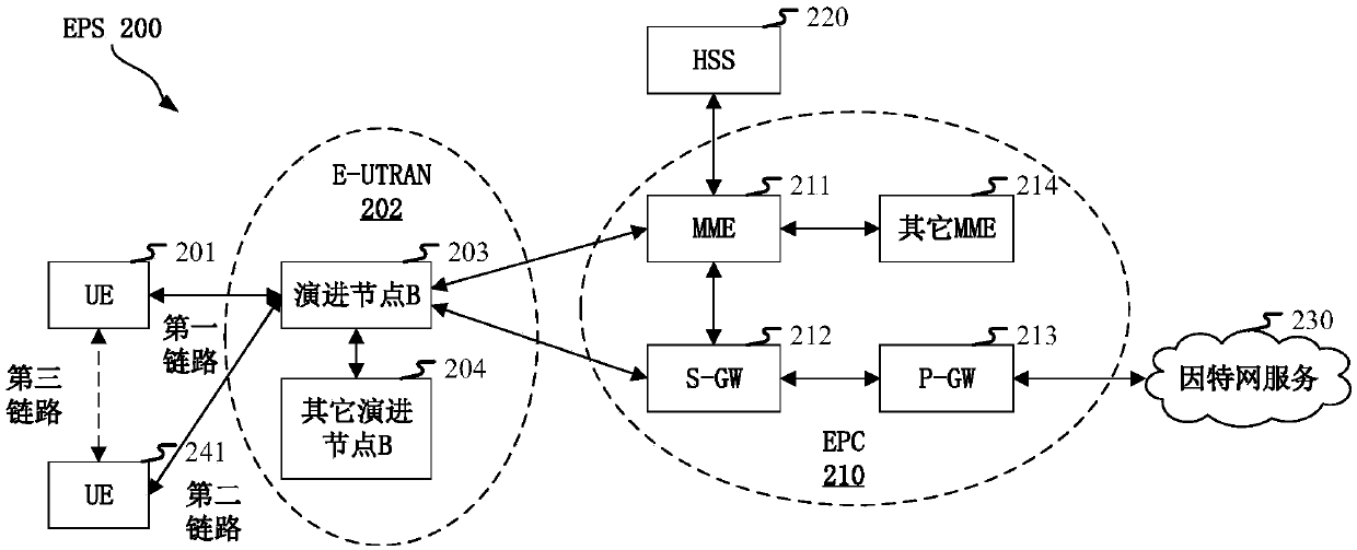
[0132] Embodiment 2 illustrates a schematic diagram of a network architecture according to the present application, as attached figure 2 shown. figure 2 It is a diagram illustrating LTE (Long-Term Evolution, long-term evolution), LTE-A (Long-Term Evolution Advanced, enhanced long-term evolution) and a future 5G system network architecture 200 . The LTE network architecture 200 may be called EPS (Evolved Packet System, evolved packet system) 200 . EPS 200 may include one or more UE (User Equipment, User Equipment) 201, E-UTRAN (Evolved UMTS Terrestrial Radio Access Network) 202, EPC (Evolved Packet Core, Evolved Packet Core) 210, HSS (Home Subscriber Server, Home Subscriber Server) 220 and Internet Services 230. Among them, UMTS corresponds to Universal Mobile Telecommunications System (Universal Mobile Telecommunications System). The EPS may be interconnected with other access networks, but these entities / interfaces are not shown for simplicity. As shown, the EPS provide...
Embodiment 3
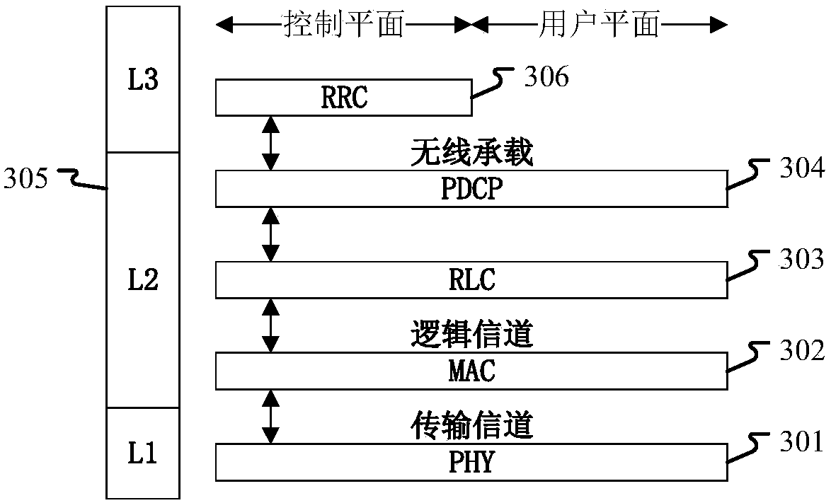
[0140] Embodiment 3 shows a schematic diagram of an embodiment of a wireless protocol architecture of a user plane and a control plane according to the present application, as shown in the attached image 3 shown. image 3 is a schematic diagram illustrating an embodiment of a radio protocol architecture for a user plane and a control plane, image 3 The radio protocol architecture for user equipment (UE) and base station equipment (gNB or eNB) is shown in three layers: layer 1, layer 2 and layer 3. Layer 1 (L1 layer) is the lowest layer and implements various PHY (Physical Layer) signal processing functions. The L1 layer will be referred to herein as PHY 301 . Layer 2 (L2 Layer) 305 is above PHY 301 and is responsible for the link between UE and gNB through PHY 301 . In the user plane, the L2 layer 305 includes MAC (Medium Access Control, Media Access Control) sublayer 302, RLC (RadioLink Control, Radio Link Layer Control Protocol) sublayer 303 and PDCP (Packet Data Conver...
PUM
 Abstract
Description
Claims
Application Information
 - R&D
- Intellectual Property
- Life Sciences
- Materials
- Tech Scout
- Unparalleled Data Quality
- Higher Quality Content
- 60% Fewer Hallucinations
Browse by: Latest US Patents, China's latest patents, Technical Efficacy Thesaurus, Application Domain, Technology Topic, Popular Technical Reports.
© 2025 PatSnap. All rights reserved.Legal|Privacy policy|Modern Slavery Act Transparency Statement|Sitemap|About US| Contact US: help@patsnap.com