Inverter current sharing method, device, inverter system and wireless charging system

A technology of inverters and multi-inverters, which is applied in the current sharing method of inverters, wireless charging systems, and devices, and can solve problems such as reduced reliability, reduced system power density, and small output current.

Active Publication Date: 2020-06-26
HUAWEI TECH CO LTD
View PDF5 Cites 0 Cited by
  • Summary
  • Abstract
  • Description
  • Claims
  • Application Information

AI Technical Summary

Problems solved by technology

[0008] When multiple high-frequency modules are connected in parallel for power supply, the parallel connection between high-frequency modules may cause uneven output current of each parallel module due to parameter differences and drive delays of each parallel module, and some modules output The current is large, and some output currents are small, which leads to inconsistent heat generation among inverters, and even causes explosions in severe cases.
[0009] The traditional technology is to reserve a larger design margin so that the module with the most serious heat generation can also meet the temperature rise requirements, but too large a redundant design will lead to a reduction in the power density and reliability of the system

Method used


Image

  • Inverter current sharing method, device, inverter system and wireless charging system
  • Inverter current sharing method, device, inverter system and wireless charging system
  • Inverter current sharing method, device, inverter system and wireless charging system

Examples


Embodiment 1

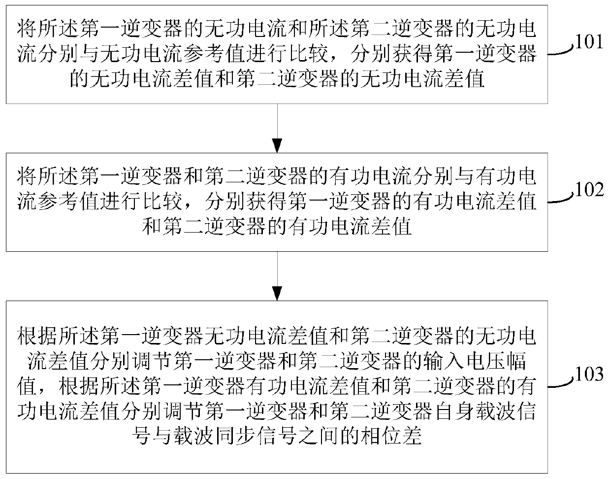
[0111] see figure 1 , is a flow chart of a current sharing method when inverters are connected in high-frequency parallel connection provided in this embodiment.

[0112] This method is applied to achieve current sharing when the output terminals of multiple inverters are connected in parallel at high frequency. The multiple inverters include at least the following two inverters: the first inverter and the second inverter, and the first inverter The output ends of the inverter and the second inverter are connected in parallel and are inductive.

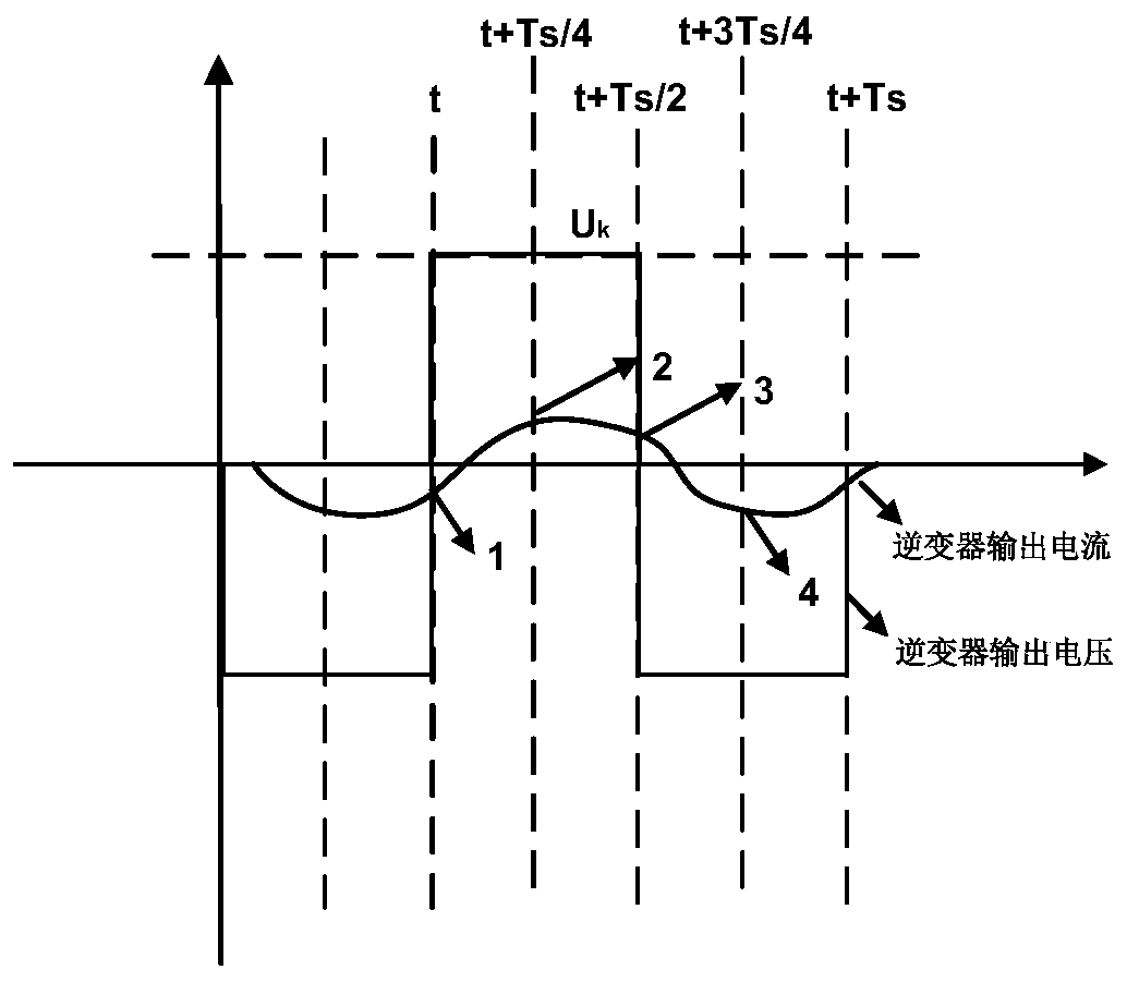
[0113] The method provided in the embodiment of this application is suitable for high-frequency parallel connection of inverters. High-frequency parallel connection means that the frequency of the output voltage of each inverter connected in parallel is the same as the switching frequency of the inverter, generally hundreds of Hz to hundreds of Hz kHz. The high frequency output voltage of the inverter is different from the power fre...

Embodiment 2

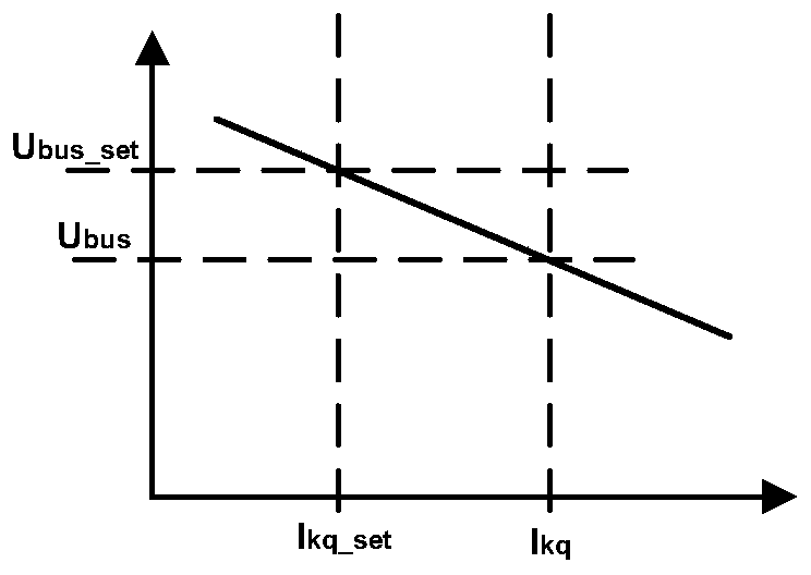
[0148] see Figure 4 , is a flow chart of the reactive current regulation method of the inverter provided in this embodiment.

[0149] This reactive current regulation method is applicable to inverters with two or more high-frequency output terminals connected in parallel. For the convenience of description, this embodiment takes the parallel connection of the output terminals of two inverters as an example for introduction. . This current sharing method includes:

[0150] Step 401: Obtain a first voltage trimming amount according to the reactive current difference of the first inverter; obtain a second voltage trimming amount according to the reactive current difference of the second inverter.

[0151] After the reactive current difference of each inverter is obtained, the reactive current difference of each inverter is input into the reactive current regulator accordingly, and after compensation processing by the reactive current regulator, corresponding to different inver...

Embodiment 3

[0165] see Image 6 , is the flow chart of the active current regulation method of the inverter provided in this embodiment. The current sharing method is suitable for inverters with two or more high-frequency output terminals connected in parallel. For the convenience of description, this embodiment In this paper, the parallel connection of the output ends of two inverters is taken as an example for introduction. This current sharing method includes:

[0166] Step 601: Obtain a first angle trimming amount according to the active current difference of the first inverter; obtain a second angle trimming amount according to the active current difference of the second inverter.

[0167] After the active current difference of each inverter is obtained, the active current difference of each inverter is input into the active current regulator accordingly, and after compensation processing by the active current regulator, the angle fine-tuning corresponding to different inverters is ...


PUM


Abstract

The present application discloses an inverter current sharing method, device, inverter system, and wireless charging system, which are used to realize multi-inverter current sharing, and the wireless charging system is used to charge electric vehicles. The method includes: The reactive current of the first inverter and the reactive current of the second inverter are respectively compared with the reactive current reference value to obtain the reactive current difference of the first inverter and the second inverter respectively; The active currents of the first inverter and the second inverter are compared with active current reference values ​​respectively, and the active current difference values ​​of the first inverter and the second inverter are respectively obtained; according to the first inverter and the second The reactive current difference of the inverters adjusts the input voltage amplitudes of the first inverter and the second inverter respectively, and adjusts the first inverter according to the active current difference of the first inverter and the second inverter. The phase difference between the carrier signal generated by the inverter and the second inverter itself and the carrier synchronization signal, so that the output currents of the two inverters can achieve current sharing.

Description

technical field [0001] The present application relates to the technical field of power electronics, and in particular to an inverter current sharing method, device, inverter system and wireless charging system. Background technique [0002] With the depletion of energy and the increasingly serious environmental pollution, the application of new energy vehicles is becoming more and more popular, such as electric vehicles. However, the charging problem of electric vehicles has become an urgent problem to be solved. At present, the development of wired charging piles is very fast, but one problem faced by charging is that the charging time of low power is relatively long. If electric vehicles can be charged as fast as gasoline vehicles, it must Increase charging power. Therefore, wired charging has been developed in the direction of 350kW and 500kW. [0003] However, the problem faced by wired charging is that wired charging requires the operator to manually plug and unplug t...

Claims


Application Information

Patent Timeline
Patent Type & Authority Patents(China)
IPC IPC(8): H02M7/48H02M7/493
CPCH02J7/025H02M7/4807H02M7/493H02M3/33573H02M7/5387H02J3/50H02J50/10H02J3/48H02J1/102H02J50/20H02J7/02H02M7/537
Inventor 毛云鹤
Owner HUAWEI TECH CO LTD
Why Eureka
Try Eureka