Phase monitoring device, phase control device of optical DQPSK receiver and its method
A phase control device and phase monitoring technology, applied in electromagnetic receivers, electrical components, electromagnetic wave transmission systems, etc., can solve the problem of excessive phase misalignment, OSNR deterioration, inability to judge whether the actual phase is greater than or less than the target value, and phase control speed limited jitter Frequency and other issues to achieve the effect of avoiding the need
- Summary
- Abstract
- Description
- Claims
- Application Information
AI Technical Summary
Problems solved by technology
Method used
Image

Examples
no. 1 approach
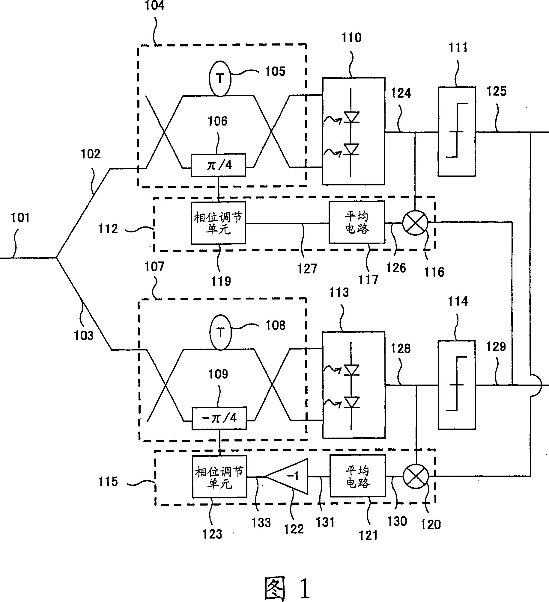
[0055] figure 1 The construction of an optical DQPSK receiver with a phase control device according to a first embodiment of the present invention is shown. Such as figure 1 As shown, the receiver has two branches, an I branch 102 and a Q branch 103 . The I branch 102 includes a Mach-Zehnder interferometer 104 , a balanced optical detector 110 , a data recovery circuit 111 and a phase control device 112 . The Q branch 103 includes a Mach-Zehnder interferometer 107 , a balanced optical detector 113 , a data recovery circuit 114 and a phase control device 115 . The upper branch of the interferometer 104 / 107 has an optical delay component 105 / 108. The duration of this delay component is the symbol period of the optical DQPSK system. The symbol period in DQPSK is equal to the bit rate divided by 2. The lower branch of the interferometer 104 / 107 has a phase shifter 106 / 109. In the I branch, the phase of the phase shifter 106 (ie, the phase shift amount of the phase shifter 10...
no. 2 approach
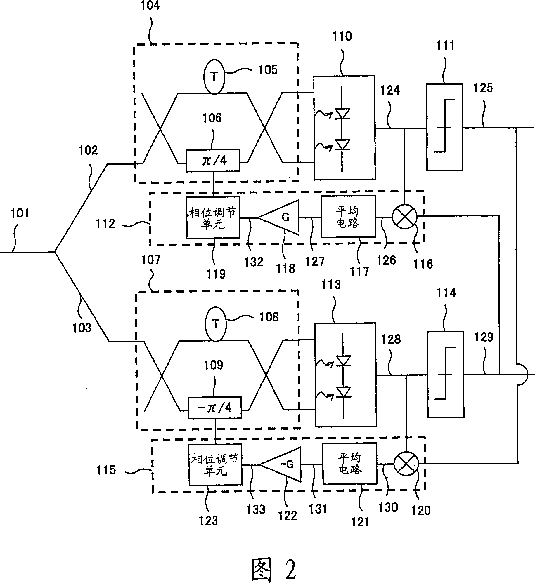
[0090] refer to figure 2 , the second embodiment of the present invention will be described. In the second embodiment, the non-inverting amplifier G (G>0) is connected in series between the average circuit 117 and the phase adjustment unit 119 of the phase control device in the I branch, and the inverting circuit of the phase control device in the Q branch The phase circuit 122 is substantially the same as that of the first embodiment except that it is composed of an inverting amplifier -G (G>0).
[0091] In this case, if the phase of the I-branch phase shifter 106 is π / 4+δ I , then it has a positive phase error δ I >0. At this time, the output 127 from the phase monitoring unit is -δ I I , and is still negative. The phase adjusting unit 119 decreases the phase of the phase shifter because the input signal is negative. Thus, the phase becomes close to the target value π / 4. If the phase shifter 106 has a negative phase error, the output of the phase monitoring unit is p...
no. 3 approach
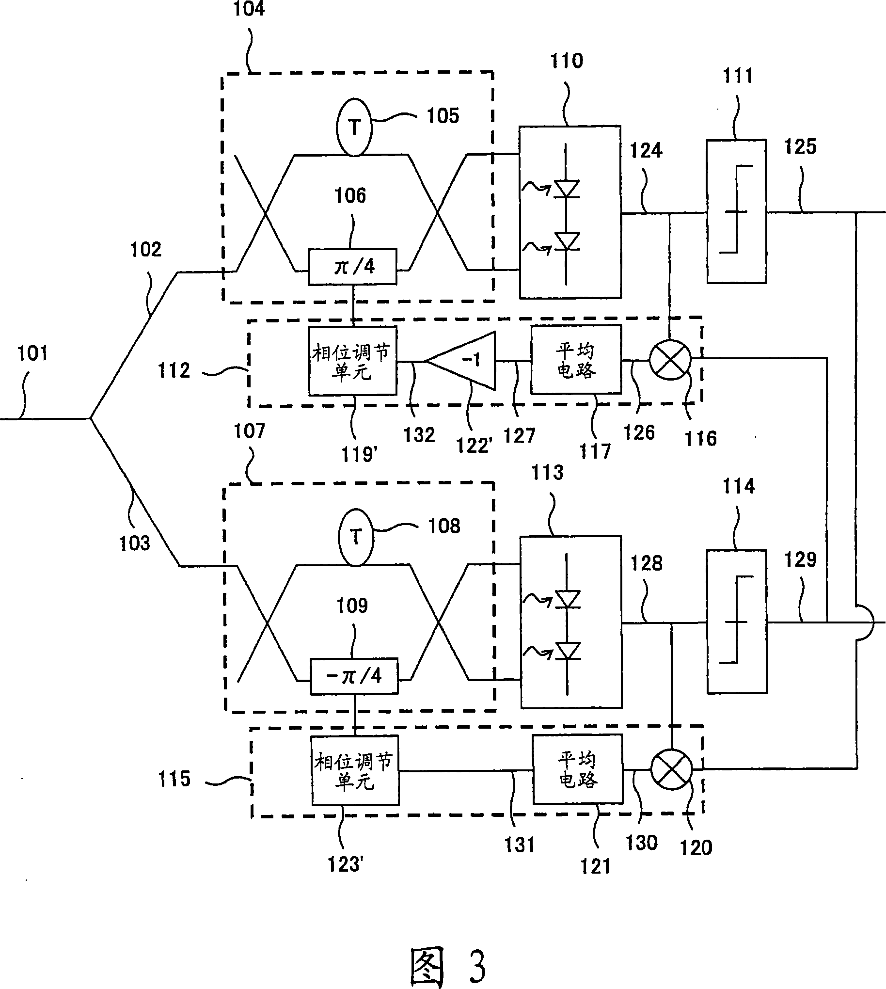
[0094] refer to image 3 , the third embodiment of the present invention will be described. In the third embodiment, the inverter circuit 122' is connected in series between the average circuit 117 and the phase adjustment unit 119 of the phase control device in the I branch, and the phase control device in the Q branch does not include the inverter circuit 122. , and the rest are substantially the same as those of the first embodiment. In addition, correspondingly, the phase adjustment unit 119' / 123' decreases the phase of the phase shifter when the phase adjustment signal is positive, and increases the phase of the phase shifter when the phase adjustment signal is negative. If the phase adjustment signal is zero, the phase adjustment unit does not act.
[0095] In this case, if the phase of the I-branch phase shifter 106 is π / 4+δ I , then it has a positive phase error δ I >0. At this time, the output 127 from the phase monitoring unit is -δ I I >0. The phase adjustmen...
PUM
 Abstract
Description
Claims
Application Information
 - R&D
- Intellectual Property
- Life Sciences
- Materials
- Tech Scout
- Unparalleled Data Quality
- Higher Quality Content
- 60% Fewer Hallucinations
Browse by: Latest US Patents, China's latest patents, Technical Efficacy Thesaurus, Application Domain, Technology Topic, Popular Technical Reports.
© 2025 PatSnap. All rights reserved.Legal|Privacy policy|Modern Slavery Act Transparency Statement|Sitemap|About US| Contact US: help@patsnap.com