Cylindrical cathode non-equilibrium magnetron plasma gas cluster source and method of use thereof
A plasma, non-equilibrium technology, applied in the fields of atomic and molecular physics and nanoscience, which can solve the problems of limited cluster yield and cluster ion yield, and achieve high-intensity and high-ionization cluster and nanoparticle beams. The effect of flow, efficient and uniform growth
- Summary
- Abstract
- Description
- Claims
- Application Information
AI Technical Summary
Problems solved by technology
Method used
Image

Examples
Embodiment 1
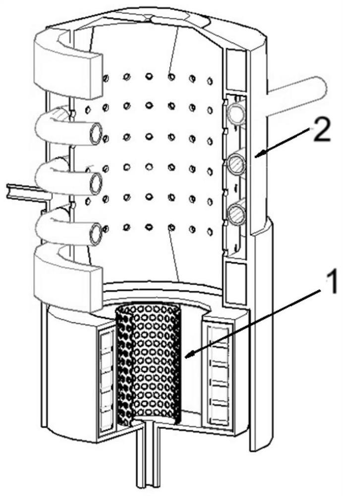
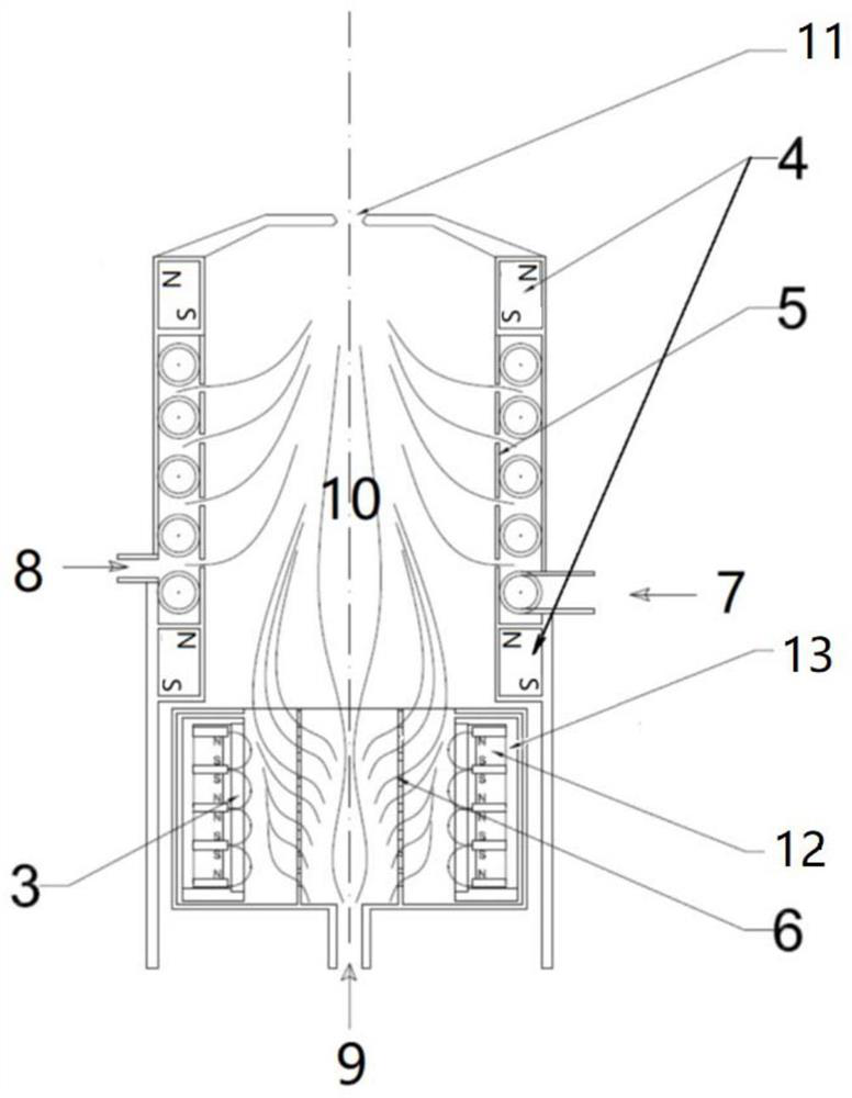
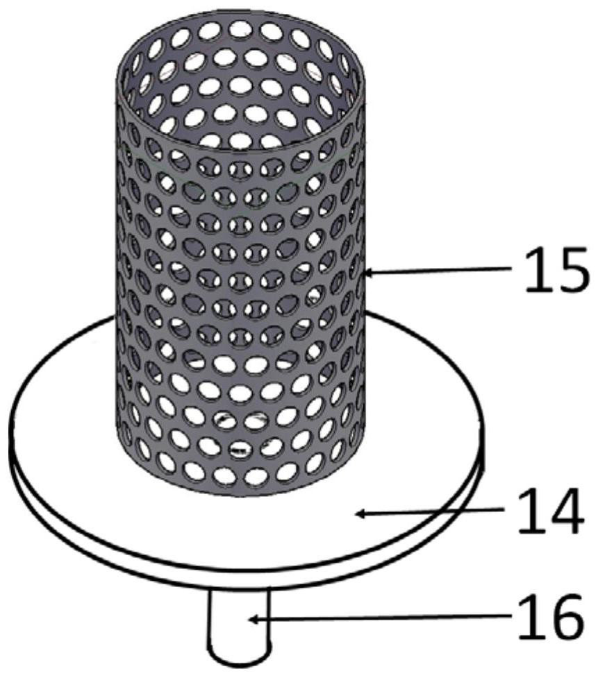
[0025] A cylindrical cathode unbalanced magnetron plasma gas cluster source, the cluster source includes a cylindrical sputtering target assembly 1 and a condensation chamber 2, and the two are connected to each other; the cylindrical sputtering target assembly 1 is sequentially arranged There is an annular cathode magnet group 12 wrapped in a sealed interlayer 13. The cylindrical sputtering target 3 and the sputtering gas are filled into the cylinder 6. The sputtering gas is filled into the bottom plate 14 of the cylinder 6 through the sputtering gas inlet 9. The vent tube 16 is filled, and flows out to the glow area between the cylindrical sputtering target 3 and the sputtering gas filling cylinder 6 through the opening on the side wall 15; the condensation chamber 2 is a vacuum-sealed chamber, and the A condensation zone 10 is formed, a nozzle 11 is provided at the center of one end of the cavity, and a differential pumping condition is formed through the nozzle 11 and the h...
Embodiment 2
[0040] A cylindrical cathode unbalanced magnetron plasma gas cluster source, the cluster source includes a cylindrical sputtering target assembly 1 and a condensation chamber 2, and the two are connected to each other; the cylindrical sputtering target assembly 1 is sequentially arranged There is an annular cathode magnet group 12 wrapped in a sealed interlayer 13. The cylindrical sputtering target 3 and the sputtering gas are filled into the cylinder 6. The sputtering gas is filled into the bottom plate 14 of the cylinder 6 through the sputtering gas inlet 9. The vent tube 16 is filled, and flows out to the glow area between the cylindrical sputtering target 3 and the sputtering gas filling cylinder 6 through the opening on the side wall 15; the condensation chamber 2 is a vacuum-sealed chamber, and the A condensation zone 10 is formed, and a nozzle 11 is provided at the center of one end of the cavity, and a differential pumping condition is formed through the nozzle 11 and t...
PUM
| Property | Measurement | Unit |
|---|---|---|
| melting point | aaaaa | aaaaa |
| thickness | aaaaa | aaaaa |
| height | aaaaa | aaaaa |
Abstract
Description
Claims
Application Information
 - R&D
- Intellectual Property
- Life Sciences
- Materials
- Tech Scout
- Unparalleled Data Quality
- Higher Quality Content
- 60% Fewer Hallucinations
Browse by: Latest US Patents, China's latest patents, Technical Efficacy Thesaurus, Application Domain, Technology Topic, Popular Technical Reports.
© 2025 PatSnap. All rights reserved.Legal|Privacy policy|Modern Slavery Act Transparency Statement|Sitemap|About US| Contact US: help@patsnap.com