Pressure machine driven by multi-connecting-rod mechanism

A technology of multi-links and presses, applied in the field of machinery, to achieve the effects of stable operation, high product precision, and heat reduction

Pending Publication Date: 2019-04-30
NANJING INST OF TECH
View PDF0 Cites 0 Cited by
  • Summary
  • Abstract
  • Description
  • Claims
  • Application Information

AI Technical Summary

Problems solved by technology

Most of the high-speed presses use the crankshaft slider mechanism as the working mechanism, and some use the sinusoidal mechanism as the working device. It is generally used for stamping the stator and rotor of the micro-motor. The rated power of the micro-motor is less than 750mW. If you want to stamp the lead frame (integrated circuit lead frame and separate lead frame), there is a flattened plane inside, and a certain electroplating process is required in the follow-up, which requires a very high flatness. Stamping such precision parts, crankshaft slider mechanism and sine mechanism and other stamping mechanisms are generally Unsatisfactory

Method used


Image

  • Pressure machine driven by multi-connecting-rod mechanism
  • Pressure machine driven by multi-connecting-rod mechanism
  • Pressure machine driven by multi-connecting-rod mechanism

Examples


Embodiment Construction

[0021] The specific implementation manners of the present invention will be described below in conjunction with the accompanying drawings.

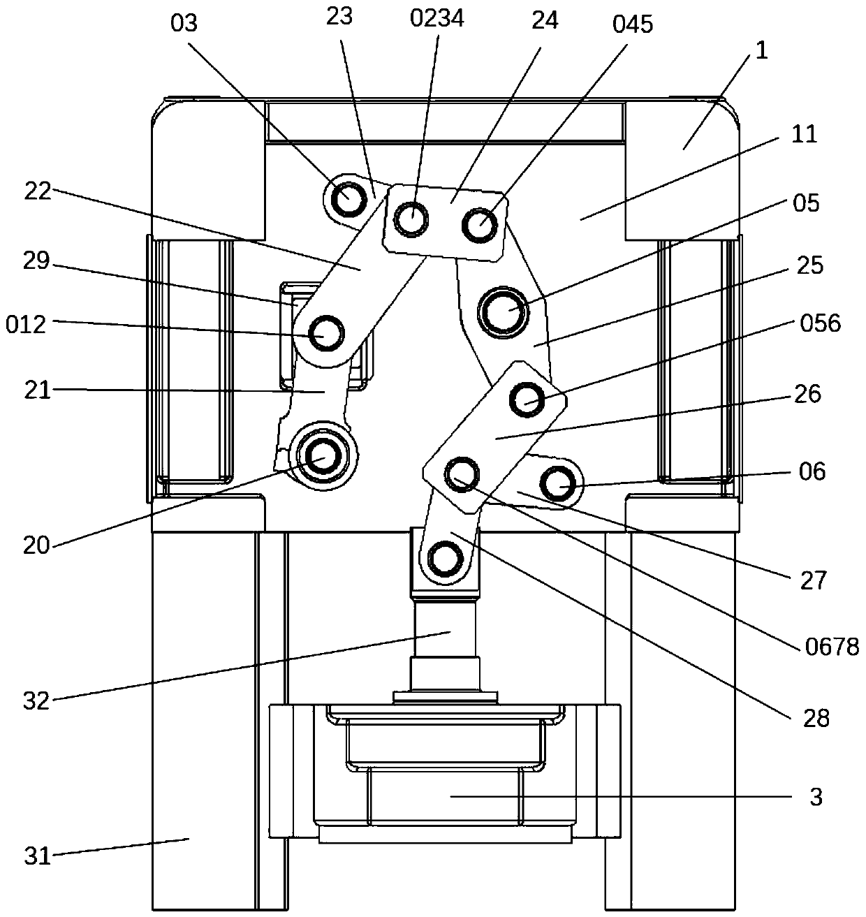
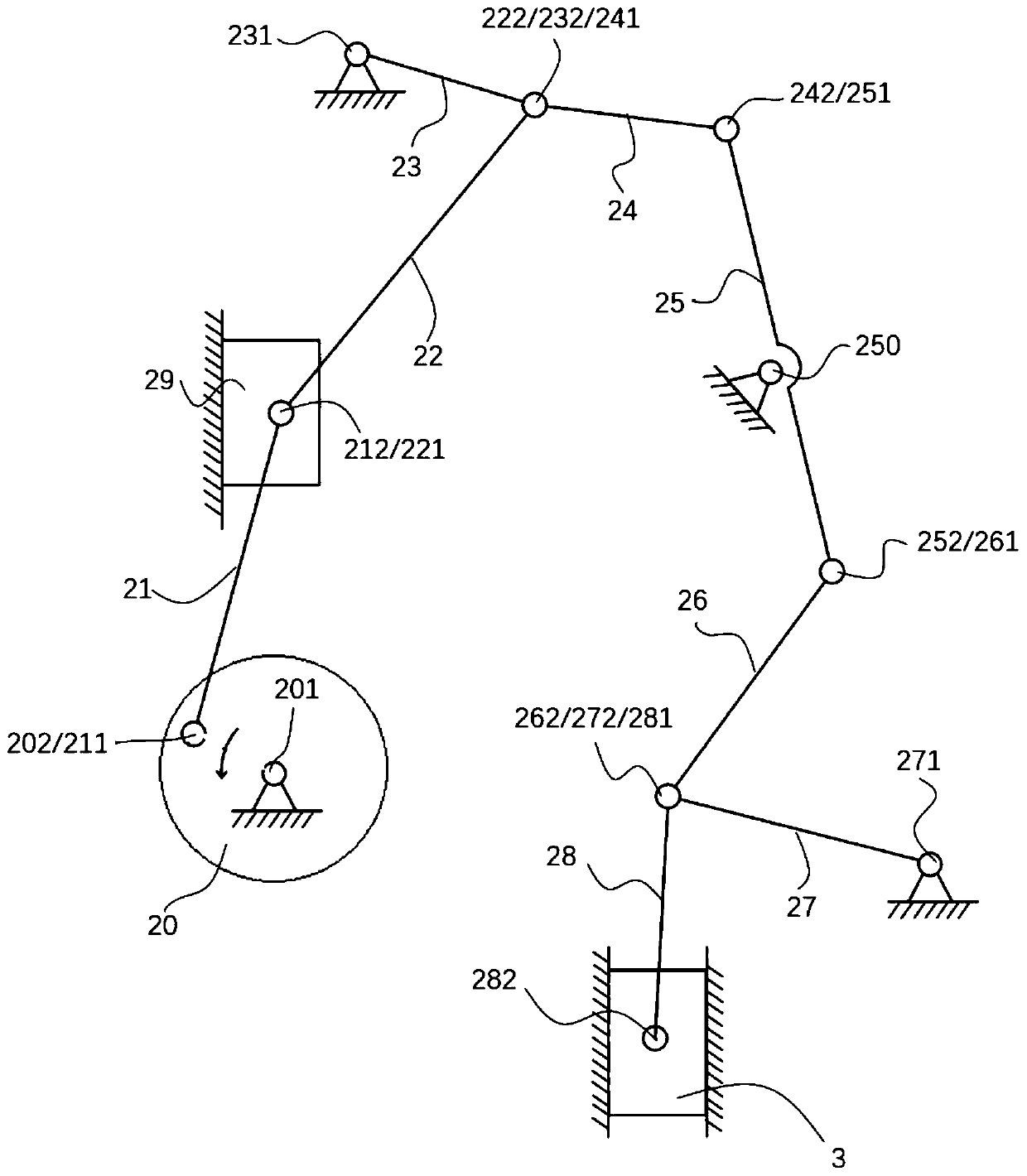
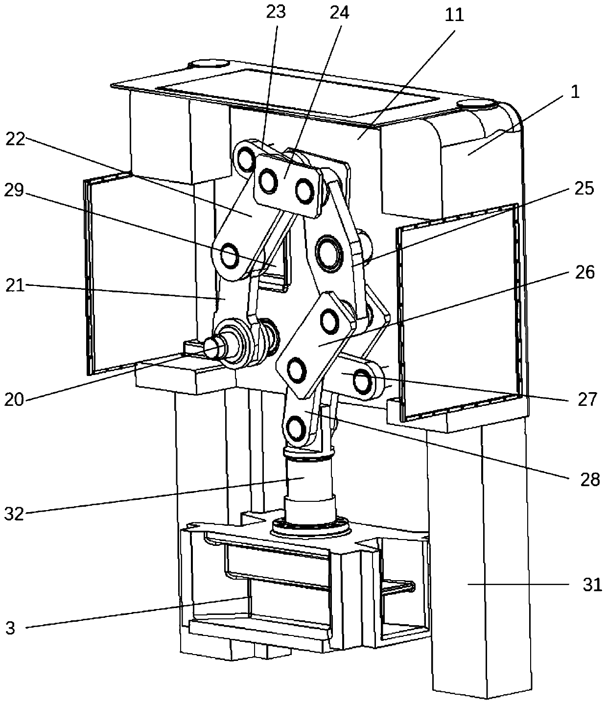
[0022] Such as Figure 1-4 As shown, the present invention provides a press machine driven by a multi-link mechanism, including a box body 1 , a mounting plate 11 , a multi-link mechanism, a stamping slider 3 , a stamping slider track 31 and a guide post 32 .

[0023] The mounting plate 11 is vertically fixed in the box body 1 .

[0024] The stamping slider track 31 is vertically fixed below the casing 1, and the stamping slider 3 can slide up and down along the stamping slider track 31.

[0025] The multi-link mechanism includes crankshaft 20, first connecting rod 21, driving slider 29, driving slider track, second connecting rod 22, A hinge shaft 012, third connecting rod 23, the Three mounting shafts 03, fourth connecting rod 24, B hinged shaft 0234, fifth connecting rod 25, fifth mounting shaft 05, C hinged shaft 045, sixth connecti...


PUM


Abstract

The invention discloses a pressure machine driven by a multi-connecting-rod mechanism. The pressure machine comprises a box body, a mounting plate, the multi-connecting-rod mechanism, a stamping sliding block and a stamping sliding block rail. The mounting plate is vertically fixed in the box body. The multi-connecting-rod mechanism comprises a crankshaft, a first connecting rod, a driving slidingblock, a driving sliding block rail, a second connecting rod, a third connecting rod, a fourth connecting rod, a fifth connecting rod, a sixth connecting rod, a seventh connecting rod and an eighth connecting rod, wherein the crankshaft is arranged on the front side of the mounting plate. An output shaft of the crankshaft makes circular motion, the first connecting rod moves along with the outputshaft, the driving sliding block is driven to move up and down, the second connecting rod is driven to move and drives the third connecting rod and the fourth connecting rod to move, the fourth connecting rod drives the fifth connecting rod to rotate, the fifth connecting rod drives the sixth connecting rod to move, the sixth connecting rod drives the seventh connecting rod and the eighth connecting rod to move, the eighth connecting rod drives the stamping sliding block to move up and down, and the moving direction of the driving sliding block is opposite to the moving direction of the stamping sliding block. The pressure machine has the advantages of being long in time for staying on a workpiece, high in stability, low in noise and the like.

Description

technical field [0001] The invention belongs to the field of machinery, and relates to a press, in particular to a press driven by a multi-link mechanism. Background technique [0002] Forging production occupies an important position in industrial production and is widely used in automobiles, precision electronics and other fields. The forging process produces workpieces with good quality, light weight, high production efficiency and low production cost. Most of the high-speed presses use the crankshaft slider mechanism as the working mechanism, and some use the sinusoidal mechanism as the working device. It is generally used for stamping the stator and rotor of the micro-motor. The rated power of the micro-motor is less than 750mW. If you want to stamp the lead frame (integrated circuit lead frame and separate lead frame), there is a flattened plane inside, and a certain electroplating process is required in the follow-up, which requires a very high flatness. Stamping such...

Claims


Application Information

Patent Timeline
Patent Type & Authority Applications(China)
IPC IPC(8): B21J9/18
CPCB21J9/18
Inventor 李钢鹿新建谭启檐陆宇豪李杰朱俊杰沈德波
Owner NANJING INST OF TECH
Why Eureka
Try Eureka