Low-noise stable permanent magnet switch reluctance motor and manufacturing process and heat dissipation method thereof

A technology of reluctance motors and permanent magnet switches, which is applied in the direction of electric components, magnetic circuit rotating parts, magnetic circuits, etc., and can solve problems such as low conduction efficiency, unstable motor rotation, and large inrush currents

Active Publication Date: 2019-04-26
NANJING YITI TECH CO LTD
View PDF8 Cites 5 Cited by
  • Summary
  • Abstract
  • Description
  • Claims
  • Application Information

AI Technical Summary

Problems solved by technology

However, the above-mentioned novel motor still has the following deficiencies: 1. When the number of "excitation salient pole pairs" on the stator and the number of "permanent magnet salient pole pairs" on the rotor are relatively small, that is, the ring-shaped permanent magnet When the distance between the salient pole pairs is large, the motor does not rotate smoothly, and there is a phenomenon of frustration; 2. When the excitation current in the excitation coil of the "excitation salient pole pair" suddenly changes direction, the rotor and stator are in the reverse flux linkage state of the magnetic circuit , the inductance in the winding is very small, which will generate a large inrush current, which will form a reverse magnetic field in the excitation coil, and this reverse magnetic field will have a demagnetization effect on the "permanent magnet salient pole pairs" on the rotor, thereby affecting Magnetic stability to permanent magnet salient pole pairs
There is an inter-turn gap between the windings of a traditional motor, and there is an air gap between the iron core and the winding. The heat conduction heat is conducted by air with high thermal resistance between the heating body winding and iron core, the heat sink casing and the stator seat. less efficient

Method used


Image

  • Low-noise stable permanent magnet switch reluctance motor and manufacturing process and heat dissipation method thereof
  • Low-noise stable permanent magnet switch reluctance motor and manufacturing process and heat dissipation method thereof
  • Low-noise stable permanent magnet switch reluctance motor and manufacturing process and heat dissipation method thereof

Examples


Embodiment 1

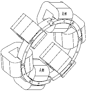
[0075] Embodiment 1, this embodiment is an air-cooled low-noise stable permanent magnet switched reluctance motor, its external shape is as attached figure 1 As shown, the structural section of this embodiment is as attached figure 2 shown.

[0076] In this embodiment, there are two stator seats 105, arranged axially opposite each other. The two stator seats 105 are fixed to the motor case 107, and the inner sides of the two stator seats 105 are respectively provided with six cavities. The cavity is arranged symmetrically and evenly centered on the axis of the motor’s rotating shaft. A number of cooling fins 104 are provided on the outer surfaces of the two stator seats 105. The C-shaped laminated iron core 112 and the excitation coil 113 form a pair of excitation salient poles. The pole pairs are respectively clamped by the upper pressing plate 111 and the lower pressing plate 114, and then embedded into the cavities inside the two stator bases respectively. The upper press...

Embodiment 2

[0086] Embodiment 2, the structure of this embodiment is basically the same as that of Embodiment 1, the only difference is that the excitation salient pole pair is composed of a C-shaped iron core, a coil bobbin and an excitation coil, see the attached Figure 13 And attached Figure 14 , the coil bobbin 171 is wrapped in a C-shaped iron core 172, and the excitation coil is wound on the coil bobbin. The coil bobbin is provided with four counterbores 170, and twelve excitation salient pole pairs are respectively embedded in the cavities inside the two stator bases. Inside the body, the screws pass through the counterbore 170 on the coil frame 171 and are fixedly connected to the stator base, and high thermal conductivity insulating glue is filled between the exciting salient pole pairs and the cavity of the stator base.

Embodiment 3

[0087] Embodiment 3, the structural section of the whole motor of this embodiment is as attached Figure 15 shown.

[0088] The structure of this embodiment is basically the same as that of Embodiment 1, the main difference is that the rotating shaft connected and fixed with the rotor bracket is a through shaft, and the structural section is as attached Figure 16 As shown, the appearance is as attached Figure 17 shown. The flange 219 of the rotating shaft and the circular pressure plate 216 clamp the rotor bracket 210 from both sides, and are riveted into a whole by rivets 217 .

[0089] In this embodiment, through the application of compound excitation salient pole pairs, the rotational torque of the motor is further increased, the power consumption is saved, and the service efficiency of the motor is improved.


PUM


Abstract

The invention relates to a low-noise stable permanent magnet switch reluctance motor and a manufacturing process and a heat dissipation method thereof. A permanent magnet circular ring is fixed to a rotor bracket of the motor, the permanent magnet circular ring is formed by an even number of stepped circular-arc-shaped permanent magnets in a head-tail oppositely matched mode, the magnetic polaritydirection of the circular-arc-shaped permanent magnets is radial, and the magnetic polarity of the adjacent circular-arc-shaped permanent magnets is different. When a double-magnetic-polarity cambered surface part section of the permanent magnet circular ring passes through a stator excitation salient pole pair, the change of magnetic acting force between the stator excitation salient pole pair and the rotor permanent magnet circular ring is obviously slowed down, and thus the motor operates more stably. Through the manufacturing process provided by the invention, a basic condition is createdfor improving the machining precision and the assembly efficiency of the motor. Various heat dissipation methods are ingeniously fused into overall design and manufacturing of the motor, convection heat dissipation of the motor structure, conduction heat dissipation of a metal material and heat-conducing heat dissipation of heat-conducting sealant are fully considered, and thus the optimal heat dissipation effect of the motor is achieved.

Description

technical field [0001] The invention relates to a permanent magnet switched reluctance motor and its manufacturing process and heat dissipation method, in particular to a permanent magnet switched reluctance motor with low noise and stable rotation speed, its manufacturing process and its heat dissipation and cooling method. Background technique [0002] Traditional permanent magnet switched reluctance motors are undergoing continuous improvement in mechanical structure and control methods. In recent years, a new type of "salient pole pair structure" motor with "excitation salient pole pair" and "permanent magnet salient pole pair" as the basic structural unit and a special excitation control method for motors with this structure have appeared in our country. . See Chinese patents CN2011104562663, CN2011104562841, CN2013105845226, CN2013105844505. This new type of motor changes and shortens the "shortest closed magnetic circuit" of the traditional permanent magnet switched...

Claims


Application Information

Patent Timeline
Patent Type & Authority Applications(China)
IPC IPC(8): H02K1/27H02K11/21H02K5/18H02K9/06H02K9/19H02K9/22
CPCH02K1/2753H02K5/18H02K9/06H02K9/19H02K9/22H02K11/21
Inventor 朱石柱司雷明武金宏戴珊珊
Owner NANJING YITI TECH CO LTD
Why Eureka
Try Eureka