
Low profile vertical polarization ultra wide band omnidirectional antenna

A vertically polarized, omnidirectional antenna technology, applied in the field of antennas, can solve problems such as large antenna structure size, achieve the effects of reducing operating frequency, reducing material loss, and improving radiation efficiency

Inactive Publication Date: 2019-04-26
XI AN JIAOTONG UNIV
View PDF3 Cites 4 Cited by
  • Summary
  • Abstract
  • Description
  • Claims
  • Application Information

AI Technical Summary

Problems solved by technology

[0003] Aiming at the deficiencies in the above-mentioned prior art, the present invention provides a low-profile vertically polarized ultra-wideband omnidirectional antenna, so as to reduce the profile and realize miniaturization under the premise of improving the antenna impedance bandwidth and ensuring the gain. The ultra-wideband omnidirectional antenna described above has a simple structure and is easy to process, effectively solving the problem of excessive size of the antenna structure in the existing ultra-wideband communication system

Method used


Image

  • Low profile vertical polarization ultra wide band omnidirectional antenna
  • Low profile vertical polarization ultra wide band omnidirectional antenna
  • Low profile vertical polarization ultra wide band omnidirectional antenna

Examples


Embodiment 1

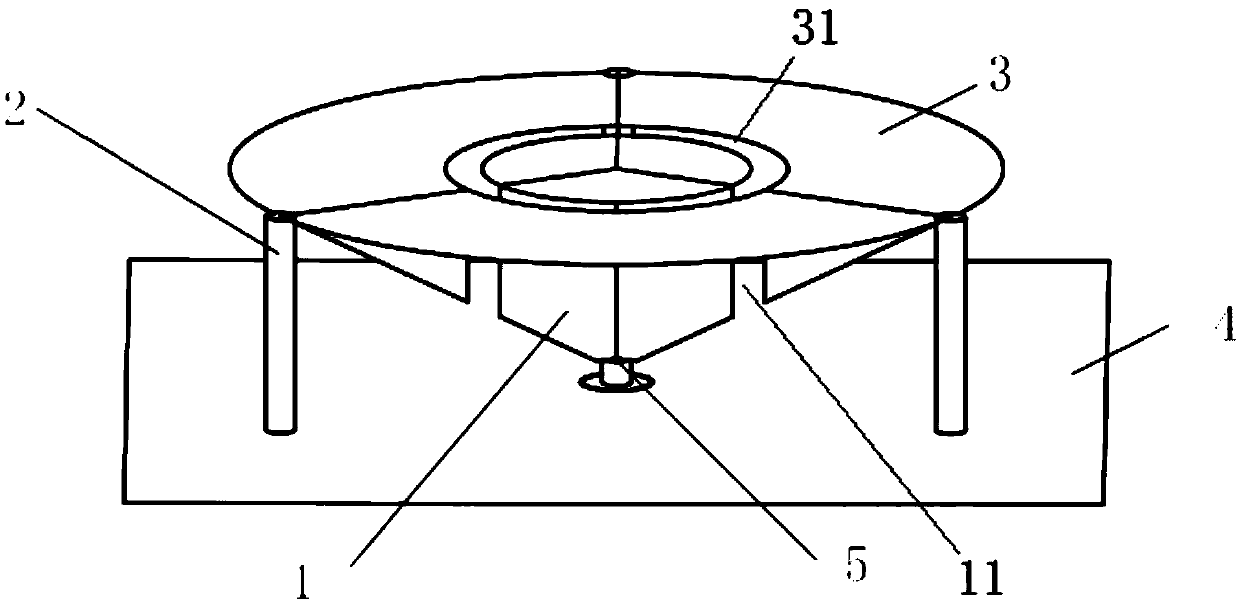
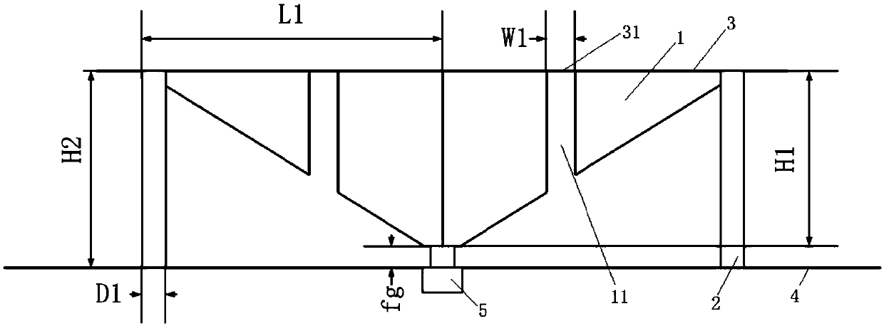
[0032] Refer to attached Figure 1-4 As shown, a low-profile vertically polarized omnidirectional antenna of the present invention includes three triangular metal sheets 1, a short-circuit metal post 2, a circular metal sheet 3, a rectangular ground plate 4 and a coaxial feeding part 5, and three triangular Metal sheet 1 includes three identical right-angled triangle metal sheets, and the shorter right-angled sides of the three right-angled triangle metal sheets are vertically arranged on the same axis; The included angle is 120°; the longer right-angle sides of the three right-angled triangle metal sheets are arranged on the upper part, and are arranged on the same plane; An annular groove 31 is arranged on it; the annular groove 31 separates the circular metal sheet 3 into an inner circular metal sheet and an outer annular metal sheet; a through groove 11 is provided on the triangular metal plate 1 corresponding to the annular groove 31, and the through groove 11 divides the...

Embodiment 2

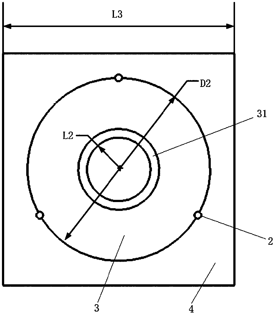
[0041] The length L1=7mm of the longer right-angled side of the right-angled triangular metal sheet, the length H1=6mm of the shorter right-angled side; the diameter D1=1mm of the short-circuit metal post 2, and the height is H2=7mm; the diameter D2=14mm of the circular metal sheet 3 , the annular groove 31 on the circular metal sheet 3 is apart from the distance L2=7mm from the center of the circular metal sheet 1, the width of the annular groove 31 is W1=0.2mm, and the through groove width W1=0.2mm on the triangular metal sheet 1; The grounding plate 4 adopts a square metal grounding plate, and the side length of the square metal grounding plate is L3=100mm; the distance between the top of the coaxial feeding part 5 and the rectangular grounding plate 4 is fg=0.5mm, and the inside The core diameter D3 = 1 mm, the inner diameter D4 of the shell 51 is 2.3 times the inner core diameter, and the thickness is t = 0.5 mm.

Embodiment 3

[0043] The length L1=20mm of the longer right-angled side of the right-angled triangle metal sheet, the length H1=15mm of the shorter right-angled side; The diameter D1=1.5mm of short-circuit metal post 2, height is H2=16mm; The diameter D2=of circular metal sheet 3= 40mm, the annular groove 31 on the circular metal sheet 3 is apart from the distance L2=10mm of the circular metal sheet 1 circle center, the width of the annular groove 31 is W1=1.5mm, the through groove width W1=1.5mm on the triangular metal sheet 1; The rectangular grounding plate 4 adopts a square metal grounding plate, and the side length of the square metal grounding plate is L3=200mm; The core diameter D3=1.5mm, the inner diameter D4 of the shell 51 is 2.3 times the inner core diameter, and the thickness is t=2mm.

[0044] The present invention adopts a fully metallized structure, which reduces the loss of antenna materials and improves the radiation efficiency of the antenna; in Embodiments 1-3, the tradit...


PUM


Abstract

The invention discloses a low profile vertical polarization ultra wide band omnidirectional antenna comprising a plurality of triangular metal pieces, short circuit metal posts, circular metal pieces,a rectangular ground plate and coaxial feeding parts. Each triangular metal piece is a right-angle triangular metal piece. The short right-angle sides of the plurality of right-angle triangular metalpieces are vertically disposed on the same axis and distributed in central symmetry. The circular metal pieces are disposed on the upper portions of the long right-angle sides of the triangular metalpieces. The ends of the long right-angle sides of the triangular metal pieces are provided with the short circuit metal posts, the upper ends of the short circuit metal posts are connected to the triangular metal pieces, and the lower ends are disposed on the rectangular ground plate. The coaxial feed parts are disposed at the lower ends of the short right-angle sides of the triangular metal pieces. The triangular metal pieces are adopted to reduce the antenna weight and reduce the antenna height effectively. Metal discs are arranged to achieve capacitive loading, and the short circuit metalposts are arranged to achieve inductive loading. The operating frequency of the antenna is effectively reduced, and the radiation efficiency of the antenna is improved.

Description

technical field [0001] The invention belongs to the technical field of antennas, in particular to a low-profile vertically polarized ultra-wideband omnidirectional antenna. Background technique [0002] Ultra-Wide Band (UWB) communication system (Ultra-Wide Band, UWB) is widely used in short-distance communication, radar and other fields due to its high transmission rate, strong anti-interference ability, low power consumption, and low cost. UWB antennas are used in communication systems It is an essential component and has a crucial impact on the performance of UWB communication systems. Since the proposal of ultra-wideband antennas, structures such as planar, multi-layer, and three-dimensional monopole antennas have been derived on the basis of traditional monopole antennas, but these structures generally have the problem of excessive size, which limits the antenna's Application scope; In recent years, with the continuous development of ultra-wideband technology and the c...

Claims


Application Information

Patent Timeline
Patent Type & Authority Applications(China)
IPC IPC(8): H01Q1/38H01Q1/48H01Q1/50
CPCH01Q1/38H01Q1/48H01Q1/50
Inventor 闫森郑颜
Owner XI AN JIAOTONG UNIV
Learn More