A kind of sensor and preparation method thereof
A sensor and force sensor technology, applied in the field of micro-electromechanical systems, can solve the problems of limited application scenarios and the inapplicability of pressure sensors, and achieve the effects of expanding application scenarios, easy calibration and mass production
- Summary
- Abstract
- Description
- Claims
- Application Information
AI Technical Summary
Problems solved by technology
Method used
Image
Examples
Embodiment 1
[0041] Embodiment 1 force sensor
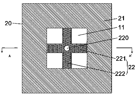
[0042] The embodiment of the present invention proposes a force sensor, including a MEMS force sensor chip. The chip includes a substrate 10 with a groove 11 on the upper surface of the substrate 10 and a pressure sensitive layer 20 on the upper surface of the substrate 10 .
[0043] The pressure sensitive layer 20 includes a frame 21 and a pressure sensitive beam 22 . The frame 21 at least partially surrounds, preferably completely surrounds the groove 11, the pressure sensitive beam 22 is formed above the groove 11 through the pressure sensitive layer 20 above the hollow groove 11, and the pressure sensitive beam 22 is suspended , the lower surface of which has a certain distance from the bottom of the groove 11 , and each end of the pressure sensitive beam 22 is in contact with the frame 21 of the pressure sensitive layer 20 respectively.
[0044] The pressure-sensitive beam 22 is a pressure-sensitive beam 22 with an axisymmetric structure ...
Embodiment 2
[0062] Embodiment 2 Preparation method of force sensor
[0063] refer to Figures 3a-3d , this embodiment proposes a method for preparing the force sensor described in Embodiment 1, comprising the following steps:
[0064] S1: Refer to Figure 3a , on the SOI substrate having the cavity 11, thin the pressure sensitive diaphragm to a predetermined thickness to form a pressure sensitive layer 20, the SOI substrate is composed of the SOI substrate 10 and the pressure sensitive diaphragm;
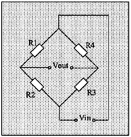
[0065] S2: Refer to Figure 3b , making four piezoresistors 23 distributed axisymmetrically or centrally symmetrically at preset positions on the upper surface of the pressure sensitive layer 20, and connecting the four piezoresistors 23 to form a Wheatstone bridge;
[0066] S3: Refer to Figure 3c , making lead holes and metal leads 224 on the pressure sensitive layer 20 based on the preset structure of the pressure sensitive beam 22 and the position of the piezoresistor;
[0067] S4. Ref...
Embodiment 3
[0081] Embodiment 3 A sensor packaged with the above-mentioned force sensor chip
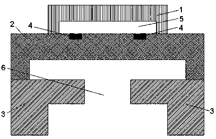
[0082] refer to Figure 4-Figure 6 , the present embodiment proposes a sensor, including the above-mentioned MEMS force sensor chip, a pressure conducting component 50 , a sensor chip containing body and an elastic component 40 .
[0083] The chip includes a substrate 10 , the upper surface of the substrate 10 has a groove 11 , and a pressure sensitive layer 20 is arranged on the upper surface of the substrate 10 .
[0084] The pressure sensitive layer 20 includes a frame 21 and a pressure sensitive beam 22 . The frame 21 at least partially surrounds, preferably completely surrounds the groove 11, the pressure sensitive beam 22 is formed above the groove 11 through the pressure sensitive layer 20 above the hollow groove 11, and the pressure sensitive beam 22 is suspended , the lower surface of which has a certain distance from the bottom of the groove 11 , and each end of the pressure sensitiv...
PUM
| Property | Measurement | Unit |
|---|---|---|
| thickness | aaaaa | aaaaa |
| width | aaaaa | aaaaa |
Abstract
Description
Claims
Application Information
 - R&D
- Intellectual Property
- Life Sciences
- Materials
- Tech Scout
- Unparalleled Data Quality
- Higher Quality Content
- 60% Fewer Hallucinations
Browse by: Latest US Patents, China's latest patents, Technical Efficacy Thesaurus, Application Domain, Technology Topic, Popular Technical Reports.
© 2025 PatSnap. All rights reserved.Legal|Privacy policy|Modern Slavery Act Transparency Statement|Sitemap|About US| Contact US: help@patsnap.com


