
Gas steam generating equipment

A technology for generating equipment and gas steam, which is applied in steam generation, steam boilers, lighting and heating equipment, etc. It can solve problems such as too many assembly joints, dry heat exchangers, and insufficient heat absorption, so as to prevent thermal deformation and damage, increase The effect of increasing the heat exchange pipeline path and heat exchange area

Pending Publication Date: 2019-04-19
广东念智节能科技有限公司
View PDF10 Cites 7 Cited by
  • Summary
  • Abstract
  • Description
  • Claims
  • Application Information

AI Technical Summary

Problems solved by technology

[0003] However, the disadvantages of this method are: the first, first, second, and third steam unit units are connected by special-shaped copper pipes, and the pipes will generate stress after being heated. Repeated use will cause certain deformations at the joints of the pipes. It is easy to leak the medium in the pipe, resulting in water leakage or air leakage.
2. There are tolerances in the processing of special-shaped connecting pipes, resulting in deviations in the hard connection between any two stages, which is not easy to assemble. Sometimes it is necessary to manually stretch or bend these special-shaped connecting pipes on site.
3. There are many assembly joints, and it takes a lot of labor
4. After the fins in the finned heat exchanger in the combustion chamber absorb heat, there is not enough refrigerant (water flowing through the pipe) to take away the heat. After being heated for a long time, the fins are easy to melt and stick, causing the heat exchanger to Uneven heating, resulting in partial dry burning of the heat exchanger, and water leakage after burning out the heat exchanger
5. The finned heat exchanger is generally composed of a plurality of stainless steel tubes welded and extended fins. There is a joint at both ends that is the inlet and outlet of each other. The pipe fittings are connected end to end to form a water flow path. The brazed arc elbow is subjected to internal high pressure after being heated during use, which is easy to crack and cause water leakage.
6. The path of cold water passing through the heat exchanger pipes is short, and the heat absorbed is not enough, resulting in low quality steam and high water content
7. Limited by the volume of the equipment and the volume of the heat exchanger, the evaporation capacity of the modular single steam generator is limited
8. The nitrogen oxides produced by traditional fire row burners far exceed the national emission standards, which is not environmentally friendly

Method used


Image

  • Gas steam generating equipment
  • Gas steam generating equipment
  • Gas steam generating equipment

Examples


Embodiment Construction

[0049] For better understanding and implementation, the specific implementation manners of the present invention will be further described in detail below in conjunction with the accompanying drawings and embodiments. The following examples are only used to illustrate the present invention and are not intended to limit the scope of the present invention.

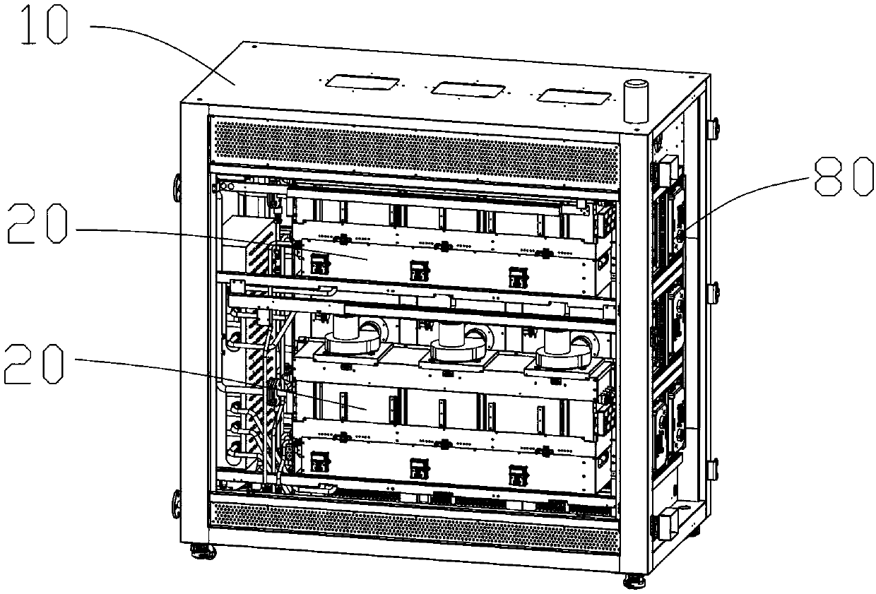
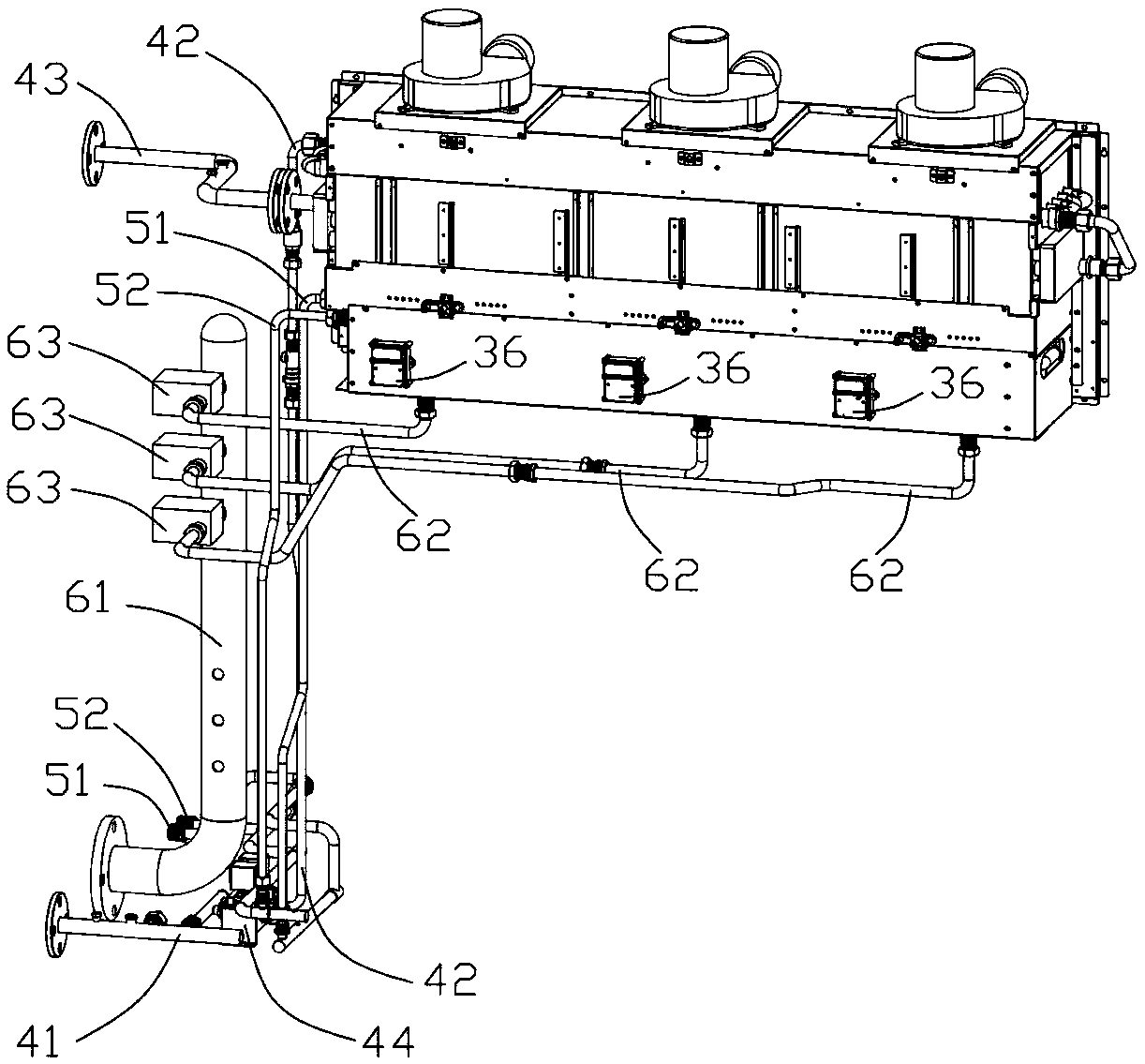
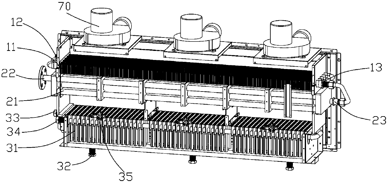
[0050] The invention discloses a gas steam generating device, such as Figure 1-3 As shown, it includes a frame 10 and more than one set of steam generating modules 20 arranged in the frame 10. In this embodiment, the number of the steam generating modules 20 is 4 groups, and they are arranged up, down, left, and right on the Inside the frame 10; the steam generating module 20 includes a combustion chamber and a finned heat exchanger 11, a shell-and-tube light tube heat exchanger 21 and a low-nitrogen fire exhaust burner arranged in the combustion chamber from top to bottom in sequence 31; one end of the finned heat exchang...


PUM


Abstract

The invention discloses gas steam generating equipment. The gas steam generating equipment comprises a machine frame and more than one set of steam generating modules arranged in the machine frame, and each steam generating module comprises a combustion chamber, a finned heat exchanger, a tube type light tube heat exchanger and a low-nitrogen fire grate burner which are sequentially arranged in the combustion chamber from top to bottom; a cold water inlet and a hot water outlet are formed in each finned heat exchanger; each tube type light tube heat exchanger is provided with a hot water inletand a steam outlet; and the hot water outlets communicate with the hot water inlets. According to the steam generating equipment, the tube type light tube heat exchanges are adopted to be arranged inthe middle layers of the combustion chambers and serve as vaporization layers, so that heat absorbed by cold water is more sufficient, and higher-quality steam can be produced. The bottom layers of the combustion chambers adopt the brand-new low-nitrogen fire grate combustors, so that the heat exchange amount is improved, and meanwhile, the generation of nitrogen oxide is reduced, and the gas steam generating equipment is energy-saving and environment-friendly.

Description

technical field [0001] The invention relates to the technical field of steam generating equipment, in particular to a gas steam generating equipment. Background technique [0002] Driven by the national "coal-to-gas" policy, gas-fired steam generating equipment has been widely used in the production and life of the people in recent years. Ordinary modular gas steam generating equipment consists of multiple groups (generally 1 to 4 groups) of steam generating modules, each group is independent of each other and can be used alone. Each group of steam generation modules is composed of three-stage steam unit units with similar structures connected by copper pipes, so that the heat exchangers in the three-stage steam unit units are connected to each other and connected in series to form a single channel. Taking the three-stage three-layer finned heat exchanger as an example, cold water enters from the top heat exchanger and flows through the first-stage top heat exchanger, the s...

Claims


Application Information

Patent Timeline
Patent Type & Authority Applications(China)
IPC IPC(8): F22B31/00F23D14/02F23D14/48F28D7/16
CPCF22B31/00F23D14/02F23D14/48F28D7/16
Inventor 田桂红
Owner 广东念智节能科技有限公司
Learn More