
Stamping production line for small-volume auto parts and method for processing parts using the production line

A technology for auto parts and production lines, applied in metal processing, metal processing equipment, manufacturing tools, etc., can solve problems such as the inability of the manipulator to grasp smoothly, the low grasping efficiency of the manipulator, and the insufficient stacking height. The effect of small space, work efficiency and work accuracy improvement

Active Publication Date: 2020-05-29
山东时风(集团)有限责任公司
View PDF7 Cites 0 Cited by
  • Summary
  • Abstract
  • Description
  • Claims
  • Application Information

AI Technical Summary

Problems solved by technology

[0003] 1) Manipulator grabbing has high quality requirements for sheet stacking. If the stacking is messy or the stacking height is not in place, the manipulator often cannot grab it smoothly, requiring workers to rearrange the stacking, which is more time-consuming and laborious;
[0004] 2) Multiple processes such as blanking, punching, stretching, flanging, trimming, and shaping need to be grasped. The efficiency of manipulator grasping is still low in actual operations. If multiple manipulators are used, a large space is required in order to expand each manipulator

Method used


Image

  • Stamping production line for small-volume auto parts and method for processing parts using the production line
  • Stamping production line for small-volume auto parts and method for processing parts using the production line
  • Stamping production line for small-volume auto parts and method for processing parts using the production line

Examples


Embodiment 1

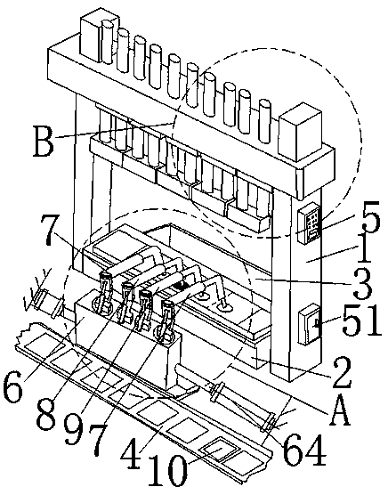
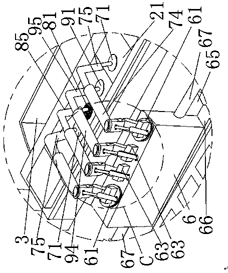
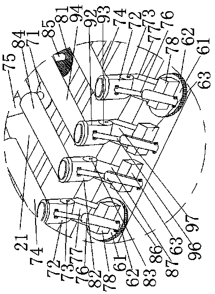
[0049] Example 1. Such as Figure 1-13 As shown, a small-volume auto parts stamping production line is characterized in that: a stamping working system, a grabbing component, a debris holding component, a conveying component, and a control system.

[0050] The stamping work system includes a frame 1, a stamping work platform 2 is arranged below the frame 1, and a number of stamping production lower molds 21 adapted to different stamping processes are arranged horizontally on the stamping work platform 2, and each stamping on each frame 1 Right above the lower mold 21 for production is provided with an upper mold 22 for stamping production corresponding to its stamping production process, and each upper mold 22 for stamping production is connected to the frame 1 through a vertical motion drive device 23 .

[0051] The grasping assembly includes a manipulator mounting base 6 arranged on the front side of the stamping work platform 2, and the manipulator mounting base 6 is insta...

Embodiment 2

[0066] Example 2, such as Figure 20 , 21 , 17, 18, the difference between this embodiment and embodiment 2 is that: the second auto parts adsorption disc 91, the debris adsorption disc 81, and the first auto parts adsorption disc 71 are vacuum type adsorption discs. Described vacuum suction disc comprises disc body 101, some suction cups 102, vacuum device 103, flexible pipe 104 that are arranged on the bottom surface of disc body 101; Vacuum device 103 comprises vacuum pump 110, vacuum generator 111, vacuum supply electromagnetic valve 105, Vacuum breaking solenoid valve 106, shut-off valve 107, vacuum switch 108, vacuum filter 109, vacuum pump 110, vacuum supply solenoid valve 105, vacuum generator 111, and vacuum filter 109 are connected in series through pipelines; vacuum filter 109 is connected through pipelines They are respectively connected to the suction cups 102 through hoses 104; the vacuum pump 110 is connected to the vacuum breaking solenoid valve 106 through th...

Embodiment 3

[0083] Example 3. Such as Figure 19 As shown, the difference between this embodiment and Embodiment 1 is that the debris storage assembly includes a debris storage box 3 , and the debris storage box 3 is arranged laterally between the stamping work platform 2 and the manipulator mounting base 6 . The progressive automatic stamping parts currently used in the industry can only satisfy flat plate parts, and are not suitable for special-shaped parts, stretched parts, and stamped deformed parts. Because the bottom surface is uneven, it cannot be pushed. The continuous stamping of various parts, and the mixed use of conveyor belts, materials and parts realizes lean production. In this embodiment, small stretched parts can be processed, and complex parts such as oil pans can also be selected.


PUM


Abstract

The invention discloses a small-size automobile part stamping production line and a stamping method thereof. The small-size automobile part stamping production line comprises a stamping working system, a grabbing assembly, a debris containing assembly, a conveying assembly and a control system, wherein the stamping working system comprises a machine frame and a stamping working platform, a plurality of stamping tools which are suitable for different stamping procedures are transversely arranged on the stamping working platform, the grabbing assembly comprises a manipulator mounting seat whichis arranged on the front side or the rear side of the stamping working platform and can transversely move, two mechanical grippers, a plurality of longitudinal cleaning manipulators and a plurality oflongitudinal grabbing manipulators are arranged on the manipulator mounting seat, and the conveying assembly comprises a conveying belt which is transversely arranged on the side, away from the stamping working platform, of the manipulator mounting seat. According to the small-size automobile part stamping production line and the stamping method thereof, multi-station automobile part stamping machining is realized through multi-mechanism coordination operation, the automation degree is higher, the working efficiency and the operation accuracy are further improved, and the labor cost of enterprises can be greatly saved.

Description

technical field [0001] The invention belongs to the technical field of automatic machining equipment for auto parts, and in particular relates to a stamping production line for small-volume auto parts and a method for processing parts with the production line. Background technique [0002] The metal stamping parts of auto parts are very important parts in the structure of the car. For example, the door, frame and the main body of the compartment of the car are all welded and assembled by stamping and forming of steel plates. The progressive automatic stamping parts currently used in the industry can only satisfy flat plate parts, and are not suitable for special-shaped parts, stretched parts, and stamped deformed parts. Because the bottom surface is uneven, it cannot be pushed. The entire stamping process can be multi-set, such as blanking, punching, stretching, flanging, trimming, shaping and other processes. In addition, due to the large output and heavy weight of the meta...

Claims


Application Information

Patent Timeline
Patent Type & Authority Patents(China)
IPC IPC(8): B21D35/00B21D43/02B21D43/10B21D43/18B21D43/12B21C51/00
CPCB21C51/00B21D35/003B21D43/026B21D43/105B21D43/12B21D43/18
Inventor 徐海港于兆申齐文君高俊峰马全军李光杰
Owner 山东时风(集团)有限责任公司
Learn More