
A mechanical magnetism-adjusting permanent magnet motor

A technology of permanent magnet motor and magnetic regulation, which is applied to electromechanical devices, magnetic circuits, synchronous machines, etc., can solve the problems of increasing the size and weight of the motor, increasing the complexity of the motor structure, and the limited power supply voltage of the inverter, achieving flexible and flexible Gap flux, omitting excitation control algorithm, small permanent magnet braking torque effect

Inactive Publication Date: 2019-04-05
HUAZHONG UNIV OF SCI & TECH
View PDF10 Cites 3 Cited by
  • Summary
  • Abstract
  • Description
  • Claims
  • Application Information

AI Technical Summary

Problems solved by technology

During the starting process, the permanent magnet magnetic field will produce a permanent magnet braking torque with the stator magnetic field, making the starting ability of the permanent magnet motor worse than that of the induction motor
[0006] (2) When the permanent magnet motor runs at high speed, a large back electromotive force will be induced on the stator winding. Due to the limited power supply voltage of the inverter, the speed range of the motor is limited
However, the mechanical magnetic adjustment device used in this motor, especially the mechanical magnetic adjustment block, is located outside the rotor, which increases the volume and weight of the motor, and also increases the complexity of the motor structure.

Method used


Image

  • A mechanical magnetism-adjusting permanent magnet motor
  • A mechanical magnetism-adjusting permanent magnet motor
  • A mechanical magnetism-adjusting permanent magnet motor

Examples


Embodiment Construction

[0032] In order to make the object, technical solution and advantages of the present invention clearer, the present invention will be further described in detail below in conjunction with the accompanying drawings and embodiments. It should be understood that the specific embodiments described here are only used to explain the present invention, not to limit the present invention. In addition, the technical features involved in the various embodiments of the present invention described below can be combined with each other as long as they do not constitute a conflict with each other.

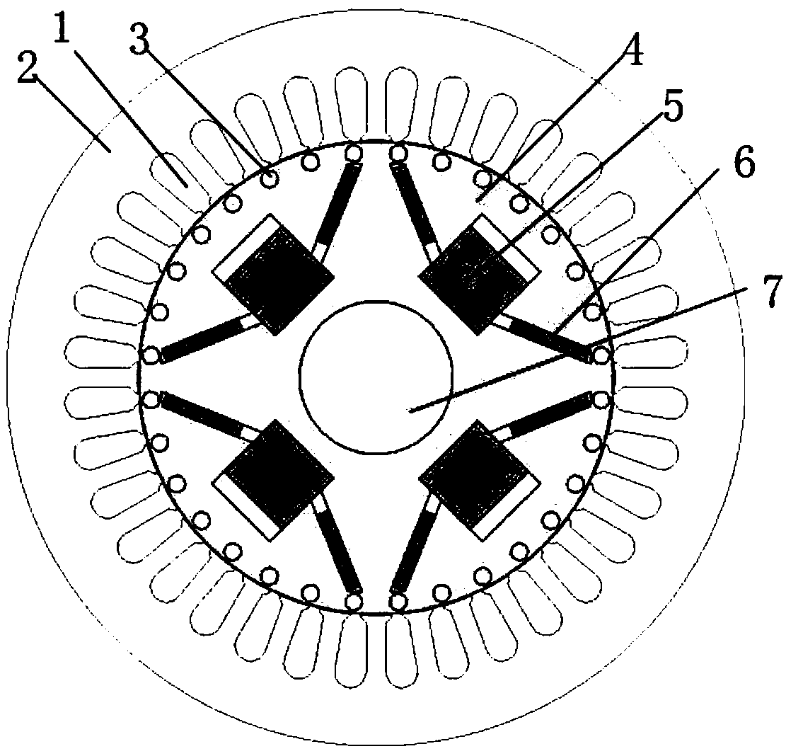
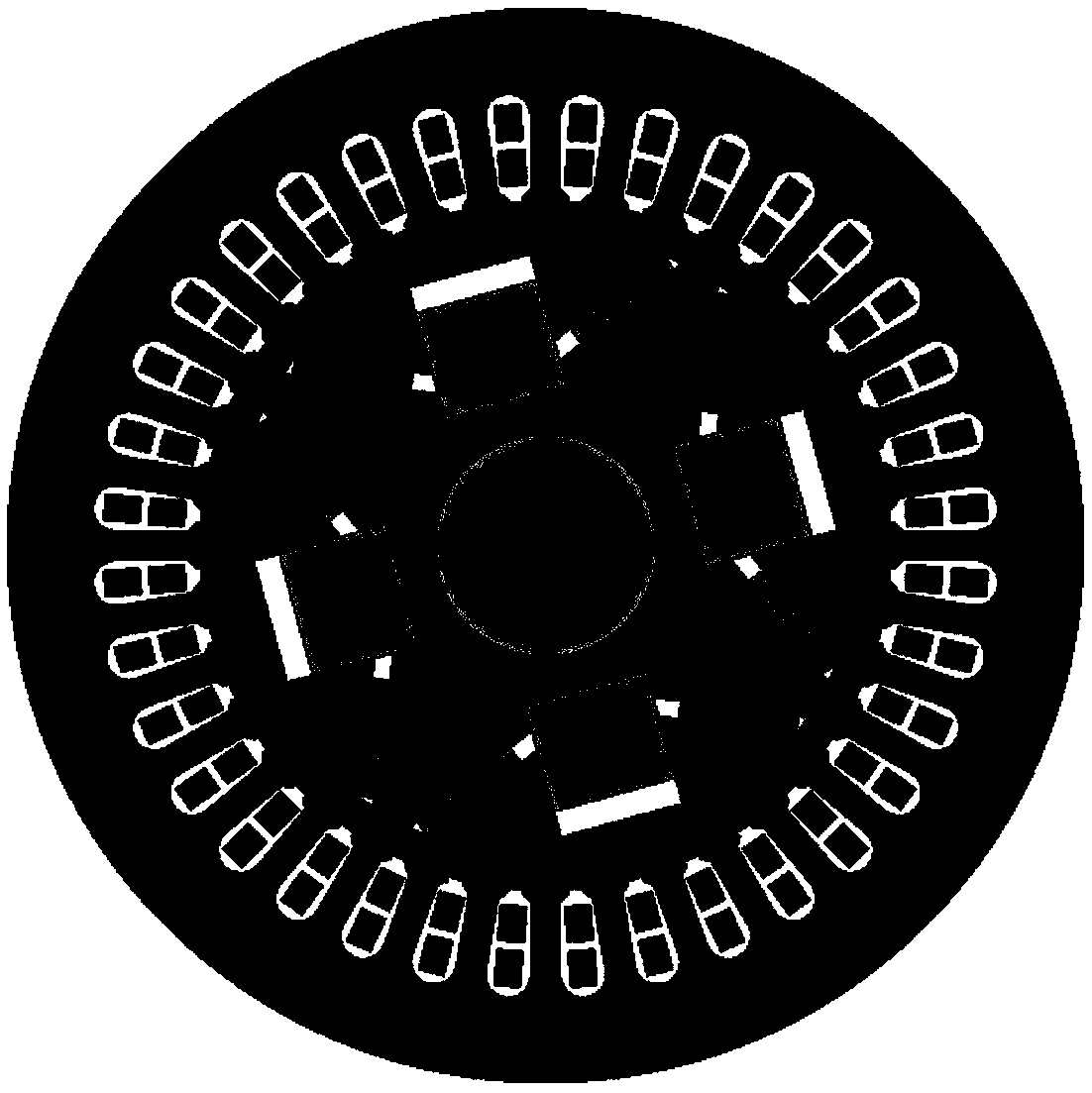
[0033] The mechanical magnetic modulation permanent magnet motor among the present invention, as figure 1 The stator part of the motor includes a set of armature windings (1) and stator core (2); the rotor part includes squirrel cage windings (3), rotor core (4), magnetic block (5) and V-shaped permanent magnet ( 6). Among them, the armature winding adopts distributed short-distance winding, a...


PUM


Abstract

The invention discloses a mechanical magnetism-adjusting permanent magnet motor comprising a rotating shaft, and a stator core and a rotor core surrounding the rotating shaft and used for mutual cooperation. A plurality of permanent magnet pairs are arranged inside the rotor core; any one pair of permanent magnets includes at least two built-in permanent magnets to form a magnetic pole, and movable magnetism-adjusting blocks are arranged between the plurality of built-in permanent magnets of any one of the permanent magnet pairs. The magnetism-adjusting blocks are used to move according to therotational speed of the rotor core. According to the invention, the overall components of the motor and the cooperation mode of the components are improved, and magnetism-adjusting units that adjustthe function of the permanent magnets are added to the rotor of the permanent magnet synchronous motor, and furthermore, the positions of the magnetism-adjusting blocks can be changed according to thespecific operation of the motor, so that the magnetic resistance of a leakage flux magnetic path of the permanent magnet flux can be reduced; permanent magnet magnetic fields in air gaps can be weakened; and the self-starting performance of the permanent magnet synchronous motor can be increased; and the flux weakening performance of the permanent magnet synchronous motor can also be improved.

Description

technical field [0001] The invention belongs to the field of motors, and more specifically relates to a mechanically adjustable magnet permanent magnet motor, which is a permanent magnet synchronous motor capable of improving the performance of starting and field-weakening speed expansion. Background technique [0002] Today, energy shortage has become an important issue related to human survival, and it is imperative to develop new energy and save energy. Electric energy is currently the most widely used secondary energy by human beings, and it is closely related to the national energy conservation, emission reduction and sustainable development strategies. With the development of the country's economy, industrial electricity consumption has increased year by year, accounting for more than 70% of the country's electricity consumption, and the electricity consumption of motors accounts for more than 50% of the total industrial electricity consumption. Therefore, the energy ...

Claims


Application Information

Patent Timeline
IPC IPC(8): H02K1/22H02K21/02H02K21/14
CPCH02K1/223H02K21/021H02K21/14H02K2213/09
Inventor 王晋徐雷敏周理兵
Owner HUAZHONG UNIV OF SCI & TECH
Learn More