
Memory and manufacturing method thereof

A manufacturing method and memory technology, applied in the direction of electric solid-state devices, semiconductor devices, electrical components, etc., can solve the problems of high process precision requirements and difficulty in controlling the production process of reducing parasitic capacitance, so as to achieve the reduction of process control precision requirements, parasitic capacitance, etc. The capacitance is easy to control and the effect of expanding the process window

Active Publication Date: 2019-04-05
YANGTZE MEMORY TECH CO LTD
View PDF4 Cites 3 Cited by
  • Summary
  • Abstract
  • Description
  • Claims
  • Application Information

AI Technical Summary

Problems solved by technology

[0005] In view of this, the present invention provides a memory and a manufacturing method thereof to solve the problems in the prior art that the manufacturing process for reducing parasitic capacitance is difficult to control and requires high process precision

Method used

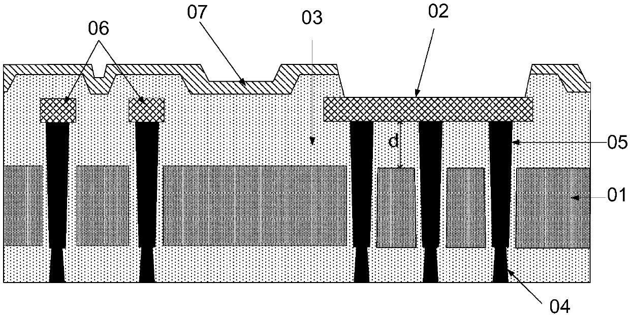
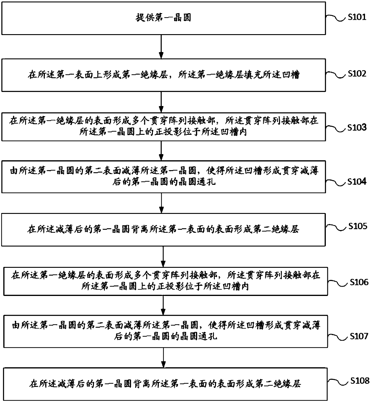
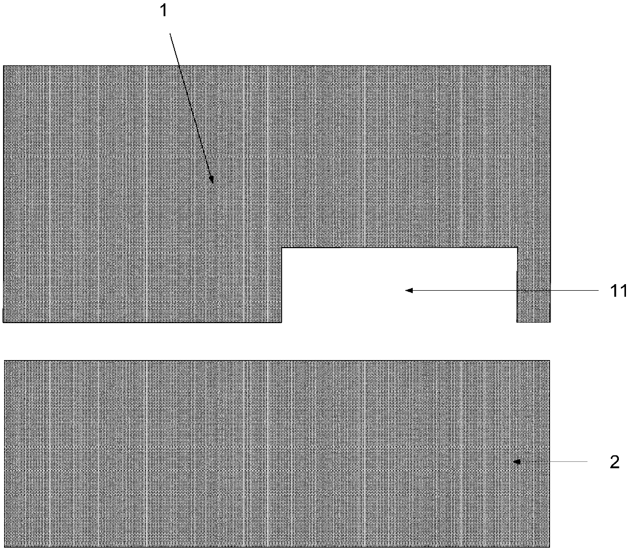

Image

  • Memory and manufacturing method thereof
  • Memory and manufacturing method thereof
  • Memory and manufacturing method thereof

Examples


Embodiment Construction

[0045] As mentioned in the background technology section, the 3D NAND manufacturing process used in the prior art to reduce parasitic capacitance is difficult to control and requires high process precision.

[0046] The invention finds that the reason for the above phenomenon is that please refer to figure 1 , figure 1 It is a schematic diagram of a cross-sectional structure of a memory; the memory includes a silicon substrate 01, an insulating layer 03 formed on both sides of the silicon substrate 01, a metal wiring 06 formed inside the silicon substrate 01, and a through-silicon contact part penetrating the substrate (through silicon contact, TSC) 05 , and a through array contact (TAC) 04 electrically connected to the TSC 05 , and a protective layer 07 is also provided on the surface of the memory structure. Wherein, a metal pad 02 is formed in a part of the protective layer 07, and the metal pad 02 is used to connect the circuit inside the memory to the chip.

[0047] Whe...


PUM


Abstract

The present application provides a memory and a manufacturing method thereof. The method comprises the steps of: providing a first wafer, wherein the first wafer is provided with a groove at a position corresponding to a position where a metal bonding pad is subsequently formed, the depth of the groove is larger than or equal to the thickness of the first wafer after thinning so as to get throughthe groove on the first wafer to form a wafer through hole penetrating the first wafer. Therefore, after the metal bonding pad is subsequently formed, the wafer through hole penetrating the first wafer is arranged at the position corresponding to the metal bonding pad, the wafer area directly facing the metal bonding pad is reduced to reduce the parasitic capacitance between the first wafer and the metal bonding pad, the groove can be formed through once etching, the depth is not needed to be strictly controlled so as to enlarge the process window to allow the mode of reducing the parasitic capacitance to be more easily controlled and reduce the process control precision requirement.

Description

technical field [0001] The invention relates to the technical field of manufacturing semiconductor devices, in particular to a memory and a manufacturing method thereof. Background technique [0002] In the new 3D NAND product structure, the memory cell area (Cell) and the peripheral area (CMOS) are fabricated on different wafers, and the circuits are connected together through a three-dimensional special process, and the wafer where the Cell is located is thinned from the back, and then the The circuit is connected. [0003] Usually in the edge area of ​​the 3D NAND chip, the internal circuit of the chip is connected by setting multiple pads, but when the pads and the internal wafer of the 3D NAND chip pass current at the same time, a strong parasitic capacitance (CIO) will be generated, reducing the Slow operation and storage speed. [0004] Therefore, reducing the parasitic capacitance between the wafer and the pad inside the 3D NAND chip has become a technical problem ...

Claims


Application Information

Patent Timeline
IPC IPC(8): H01L27/11551H01L27/11578
CPCH10B41/20H10B43/20
Inventor 陈赫陈俊华子群董金文朱继锋肖亮王永庆
Owner YANGTZE MEMORY TECH CO LTD
Learn More