Chip-free pipe cutter with adjustable cutting length
A technology for cutting lengths and pipe cutting machines, which is applied in the direction of pipe shearing devices, shearing devices, and attachments of shearing machines, etc. It can solve the problem that the length of pipe fittings cannot be guaranteed to be consistent, and achieve the effect of saving the number of workers and reducing the amount of labor
- Summary
- Abstract
- Description
- Claims
- Application Information
AI Technical Summary
Problems solved by technology
Method used
Image

Examples
Embodiment 1
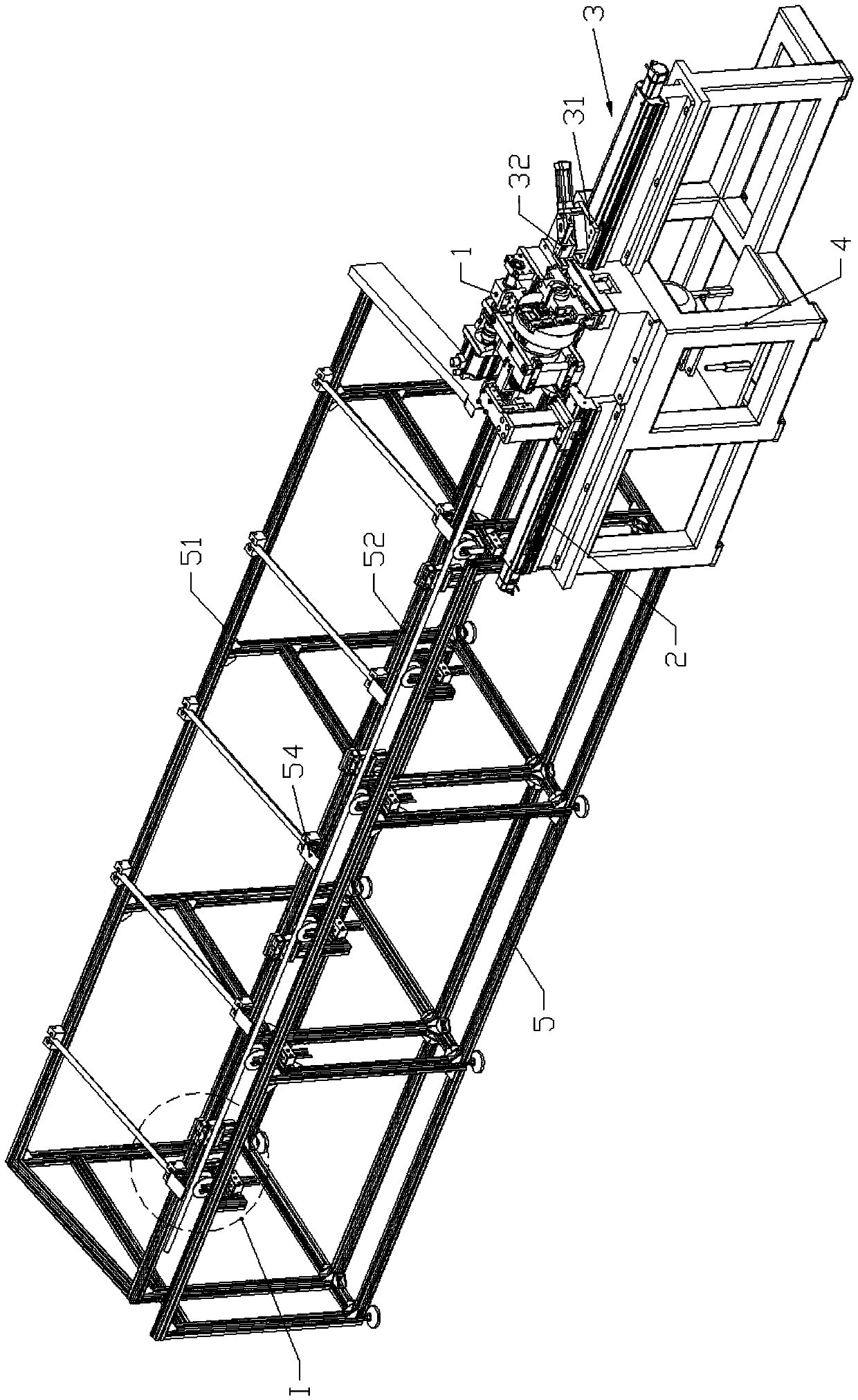
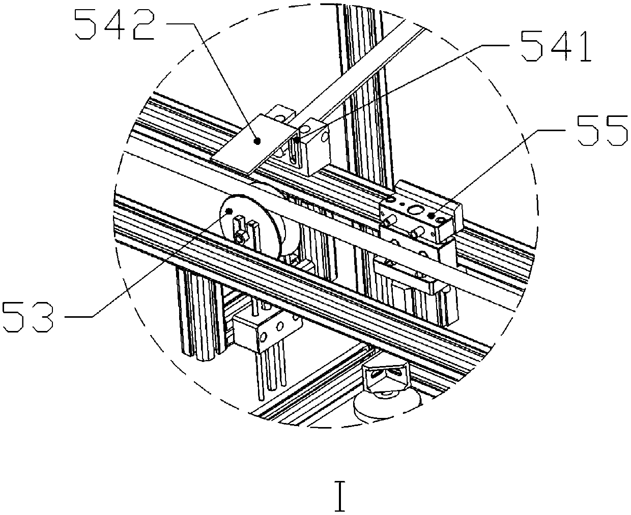
[0026] Chipless pipe cutter with adjustable cutting length, such as Figure 1-6 As shown, it includes a material rack mechanism 5, which is fixedly installed on the bed body 4 at one end of the material rack mechanism 5 along the length direction. The pipe cutting main shaft mechanism 1 and the fixed-length mechanism 3 used to limit the cutting length of the pipe fittings; the material rack mechanism 5 is a rectangular parallelepiped frame; the material rack mechanism 5 is equipped with a plurality of A fixed pulley 53 for guiding pipe fittings; the rack mechanism 5 is provided with a lower rod 52 on one side of the fixed pulley 53; a higher rod 51 is arranged on a side far away from the fixed pulley 53 of the rack mechanism The high pole 51 is 10-20cm higher than the low pole 52; the pulling mechanism 2 includes a strip-shaped pulling base 21 fixedly connected to the bed body 4 and a floating clamp for clamping pipe fittings Claw mechanism 23; said floating jaw mechanism 23 ...
Embodiment 2
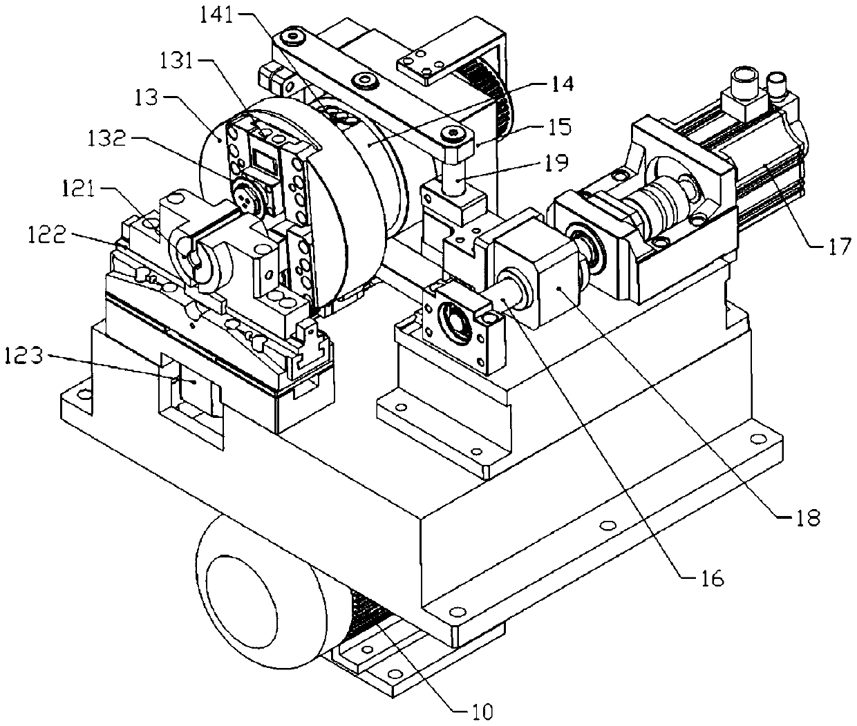
[0034] Two T-shaped sliders 131 are slidably connected to the flange 13 in the radial direction; the two T-shaped sliders are collinear; a tool 132 is fixedly connected to the T-shaped sliders 131 .
[0035] The main shaft 11 is also sleeved with a shift fork connection plate 14; the shift fork connection plate 14 moves along the axial direction of the main shaft 11 without relative rotation, such as by setting strip-shaped protrusions in the axial direction on the outer periphery of the main shaft 11; The shift fork connecting plate 14 is fixedly connected with a shift fork 141 toward the flange 13; the shift fork 141 is provided with a chute 1411; the T-shaped slider 131 is fixedly connected with a Cross bar: the T-shaped slide block 131 is driven by the movement of the shift fork connecting plate 14 along the main shaft 11 so that the tool 132 moves in the radial direction to realize the feeding of the tool 132 .
[0036] The main shaft 11 is located on the side of the shif...
Embodiment 3
[0039] The material pulling mechanism 2 also includes a second screw rod arranged along the length direction of the material pulling base 21 and a third motor 22 for driving the rotation of the second screw rod; the material pulling base 21 is slidably connected with Sliding table 24; on the sliding table 24, a threaded hole is formed corresponding to the second screw rod to be threadedly connected with the second screw rod; the floating jaw mechanism 23 is fixedly connected to the sliding table 24 The floating jaw mechanism 23 includes a two-way air cylinder 25 fixedly connected to the slide table 24 and two jaws 26 fixedly connected to two output ends of the two-way air cylinder respectively; The bottom of the two-way cylinder; each jaw 26 is formed with an arc-shaped groove towards the middle side; the bottom of each jaw 26 is fixedly connected with a lifting plate 27 towards the side of the pipe fitting; two lifting plates 27 Symmetrically crossed and the bottom surface is...
PUM
 Abstract
Description
Claims
Application Information
 - R&D Engineer
- R&D Manager
- IP Professional
- Industry Leading Data Capabilities
- Powerful AI technology
- Patent DNA Extraction
Browse by: Latest US Patents, China's latest patents, Technical Efficacy Thesaurus, Application Domain, Technology Topic.
© 2024 PatSnap. All rights reserved.Legal|Privacy policy|Modern Slavery Act Transparency Statement|Sitemap