Adjacent segmented mirror detection method and detection system

A detection method and imaging system technology, applied in the field of optics, can solve problems such as difficult splicing and alignment of splicing mirrors, and achieve the effects of convenient disassembly and maintenance, easy operation, and high precision

Active Publication Date: 2019-04-02
CHANGCHUN INST OF OPTICS FINE MECHANICS & PHYSICS CHINESE ACAD OF SCI
View PDF11 Cites 7 Cited by
  • Summary
  • Abstract
  • Description
  • Claims
  • Application Information

AI Technical Summary

Problems solved by technology

[0006] Embodiments of the present invention provide a detection method and detection system for adjacent splicing mirrors, so as to at least solve the technical problem of difficult splicing alignment of existing splicing mirrors

Method used


Image

  • Adjacent segmented mirror detection method and detection system
  • Adjacent segmented mirror detection method and detection system
  • Adjacent segmented mirror detection method and detection system

Examples


Embodiment 1

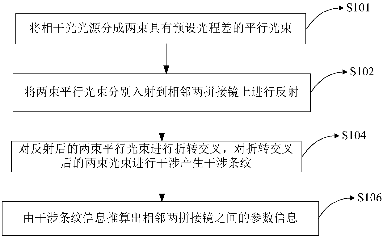
[0046] According to an embodiment of the present invention, a method for detecting adjacent spliced ​​mirrors is provided, which is suitable for confocal / co-phase spliced ​​mirrors, see figure 1 , including the following steps:

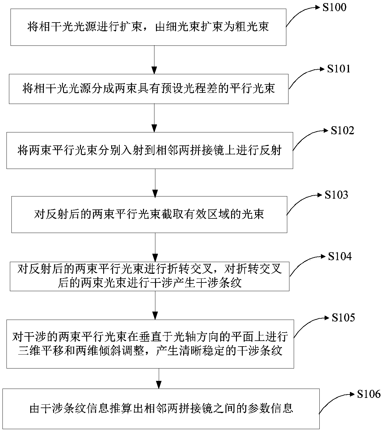
[0047] S101: Divide the coherent light source into two parallel beams with a preset optical path difference;

[0048] S102: two beams of parallel light beams are respectively incident on two adjacent splicing mirrors for reflection;

[0049] S104: Folding and crossing the reflected two beams of parallel beams, and interfering the two beams after the deflection and crossing to generate interference fringes;

[0050] S106: Deduce the parameter information between two adjacent splicing mirrors from the interference fringe information.

[0051]In the method for detecting adjacent splicing mirrors in the embodiment of the present invention, the parameter information between two adjacent splicing mirrors is calculated from the interference fringe informat...

Embodiment 2

[0062] According to another embodiment of the present invention, see Figure 4 , provides an adjacent stitching mirror detection system, comprising:

[0063] Laser 1, used to generate a coherent light source;

[0064] The beam splitter is used to split the coherent light source into two parallel beams with a preset optical path difference and incident them on two adjacent splicing mirrors for reflection;

[0065] The beam interferometer is used to fold and cross the reflected two beams of parallel beams, and interfere the two beams of folded and crossed beams to generate interference fringes;

[0066] The parameter calculation unit is used to calculate the parameter information between two adjacent splicing mirrors from the interference fringe information.

[0067] As a preferred technical solution, the beam splitter includes: a right-angled triangular prism 3, a parallelogram prism 5, the right-angled triangular prism 3 is glued to the parallelogram prism 5 whose angle is c...


PUM


Abstract

The invention relates to the field of optics, in particular to an adjacent segmented mirror detection method and detection system. The method and system comprise the following steps of: dividing the coherent light source into two parallel light beams having a predetermined optical path difference; enabling the two parallel light beams to be respectively incident on the two adjacent segmented mirrors for reflection; folding and crossing the two parallel light beams after reflection, and interfering the two light beams after the folding and crossing to generate interference fringes; and calculating the parameter information between two adjacent segmented mirrors according to the interference fringe information. Compared with an existing edge sensor detection method, the method is higher in precision, convenient to detach and maintain and free of being affected by environmental temperature, humidity, dust and the like. Moreover, the method is easy to operate during the adjustment process,and solves the problem that the traditional edge sensor is susceptible to environmental temperature, humidity, dust and the like. The method is suitable for segmented telescope mirrors that require high-precision confocal co-alignment. The structure is simple, the feasibility is strong, the installation is convenient, and the unit integration function is provided.

Description

technical field [0001] The invention relates to the field of optics, in particular to a detection method and detection system for adjacent splicing mirrors. Background technique [0002] The resolution of ground-based telescopes is related to factors such as atmospheric turbulence, observation wavelength, and effective aperture of the telescope. Assuming that the environment where the telescope is located is stable due to atmospheric turbulence and the observation wavelength is fixed, the resolution of the telescope is proportional to the effective aperture of the telescope. However, with the continuous development of astronomical exploration technology, in order to explore fainter distant targets, The aperture of the telescope needs to be continuously increased, but due to the constraints of practical factors such as processing and manufacturing, handling and adjustment, technical difficulty, and system reliability, the aperture of a single-aperture telescope cannot be infi...

Claims


Application Information

Patent Timeline
Patent Type & Authority Applications(China)
IPC IPC(8): G01B11/00
CPCG01B11/00
Inventor 安其昌曹海峰杨飞张景旭
Owner CHANGCHUN INST OF OPTICS FINE MECHANICS & PHYSICS CHINESE ACAD OF SCI
Why Eureka
Try Eureka