Eureka AIR delivers breakthrough ideas for toughest innovation challenges, trusted by R&D personnel around the world.

Single-fiber ultrahigh-precision time transmission method

A time-transfer, high-precision technology, applied in time-division multiplexing systems, electrical components, multiplexing communications, etc., can solve problems such as slow delay drift and drift accumulation, automatic dynamic compensation circuits are complicated, and cannot be solved , to achieve significant economic benefits and good market prospects

Active Publication Date: 2014-01-29
四川泰富地面北斗科技股份有限公司
View PDF7 Cites 19 Cited by
  • Summary
  • Abstract
  • Description
  • Claims
  • Application Information

AI Technical Summary

Problems solved by technology

[0004] In order to solve the existing time and frequency synchronization technology of optical fiber communication network, due to the inherent pointer adjustment of SDH network elements, asymmetric two-way delay and other factors, it is difficult to realize the transmission of high-precision time signals, and the slow change of optical fiber transmission delay cannot be controlled , the circuit to realize automatic dynamic compensation is relatively complex and cannot solve the problems of extremely slow time delay drift and drift accumulation. The present invention proposes a single-fiber ultra-high-precision time transfer method

Method used


Image

  • Single-fiber ultrahigh-precision time transmission method
  • Single-fiber ultrahigh-precision time transmission method
  • Single-fiber ultrahigh-precision time transmission method

Examples


Embodiment Construction

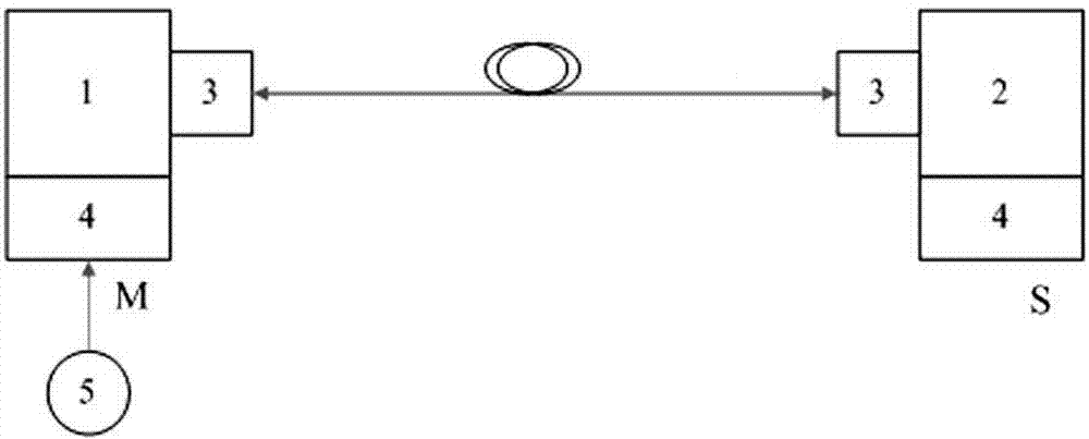
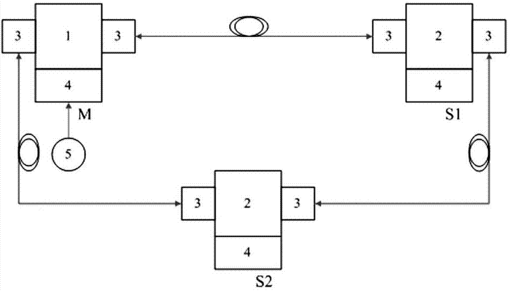
[0026] attached figure 1 It is a schematic diagram of the point-to-point structure of the single-fiber ultra-high-precision time transfer method of the present invention. In the figure, 1 is the master time synchronization device, 2 is the slave time synchronization device, 3 is the single-fiber bidirectional optical transceiver module, and 4 is the delay processing module. 5 is the cesium atomic clock, M is the master station, and S is the slave station. As can be seen from the figure, the single-fiber ultra-high-precision time transfer method of the present invention connects the single-fiber bidirectional optical transceiver module 3, the delay processing module 4 and the master time synchronization device 1 or slave time synchronization device 2 respectively at both ends of the same optical fiber, and A cesium atomic clock 5 is connected to the master time synchronization device 1 side; the optical fiber delay value and its change value between the master and slave time sy...


PUM


Abstract

The invention provides a single-fiber ultrahigh-precision time transmission method and aims to solve the problems that slow change in fiber transmission delay is uncontrollable and the extremely slow delay drift and drift accumulation cannot be solved in the existing fiber communication network time frequency synchronization technology. A single-fiber bidirectional optical transceiving module, a delay processing module and a master time synchronization device or slave time synchronization device are respectively connected to two ends of a same fiber. A cesium atomic clock is connected to the side of the master time synchronization device. Fiber delay between the master and slave time synchronization devices and a change value of the fiber delay are precisely measured and compensated. The method has the advantages that the problems that drift and drift accumulation caused by the extremely slow change in fiber transmission delay along with time, temperature, fiber ageing and the like cannot be eliminated in the prior art are solved; time synchronization precision is controlled in the range of + / -5 nanoseconds, networking can be in any form, and the method has promising market prospect and significant economic benefit.

Description

technical field [0001] The invention relates to a time-frequency synchronization technology of an optical fiber communication network, in particular to a single-fiber ultra-high-precision time transfer method. Background technique [0002] With the continuous development of optical fiber communication technology, extremely accurate time-frequency synchronization technology (≤1ns, ≤1E-13 / day, which is 100 times higher than the existing time-frequency accuracy) has become a frontier topic of time-frequency research all over the world. However, in the currently operating time-frequency synchronization network, it is difficult to achieve ultra-high-precision time-frequency synchronization because the time-frequency signal is greatly damaged during the transmission process of the optical fiber communication network. At present, as a transmission network, SDH network of optical synchronous digital system occupies a large proportion in my country's communication, electric power and...

Claims


Application Information

Patent Timeline
Patent Type & Authority Applications(China)
IPC IPC(8): H04J3/06
Inventor 李忠文李高峰孟志才李有生李琦彭良福
Owner 四川泰富地面北斗科技股份有限公司
Why Eureka
Eureka Blog
Learn More