
Temperature compensation structure based on array waveguide grating

An arrayed waveguide grating and temperature compensation technology, applied in the field of optical communication, can solve problems such as inability to perform secondary compensation and difficult to meet

Pending Publication Date: 2019-03-29
HYC CO LTD
View PDF1 Cites 0 Cited by
  • Summary
  • Abstract
  • Description
  • Claims
  • Application Information

AI Technical Summary

Problems solved by technology

Therefore, these compensation methods can only maintain wavelength stability in a limited temperature range, and it is difficult to meet the requirements for applications with large temperature ranges such as outdoors.
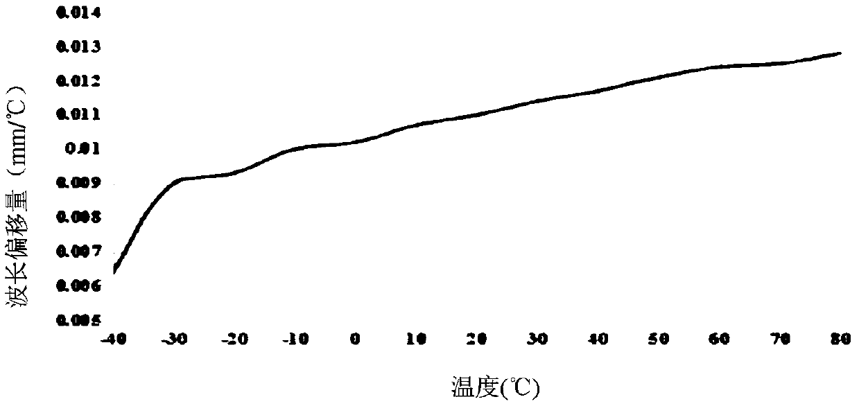
In order to solve the above problems, the patent application document with the publication number CN101576637B proposes a temperature compensation structure capable of secondary compensation, but the compensation of this structure is symmetrical, that is, when the temperature is cold and shrinks, the lower the temperature, the greater the movement change. Small, when thermal expansion, the higher the temperature, the smaller the movement change, which is inconsistent with the temperature characteristic curve of the arrayed waveguide grating chip, so effective secondary compensation cannot be performed

Method used


Image

  • Temperature compensation structure based on array waveguide grating
  • Temperature compensation structure based on array waveguide grating
  • Temperature compensation structure based on array waveguide grating

Examples


Embodiment Construction

[0014] The present invention will be further described in detail below in conjunction with the accompanying drawings and embodiments. It should be understood that the specific embodiments described here are only used to explain the present invention, but not to limit the present invention. In addition, it should be noted that, for the convenience of description, only parts related to the present invention are shown in the drawings but not all content. Before discussing the exemplary embodiments in more detail, it should be mentioned that some exemplary embodiments are described as processes or methods depicted as flowcharts. Although the flowcharts describe various operations (or steps) as sequential processing, many of the operations may be performed in parallel, concurrently, or simultaneously. In addition, the order of operations can be rearranged. The process may be terminated when its operations are complete, but may also have additional steps not included in the figure...


PUM


Abstract

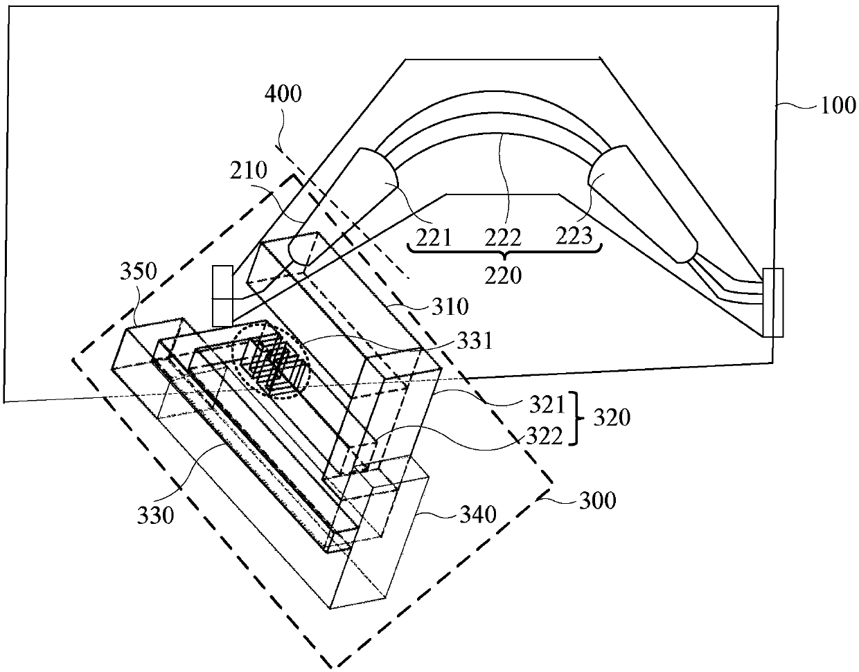
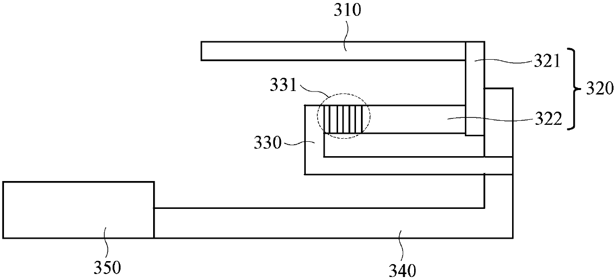
The invention discloses a temperature compensation structure based on an array waveguide grating. The temperature compensation structure based on the array waveguide grating comprises a bottom plate,an array waveguide grating chip and a two-stage temperature compensation structure, wherein the array waveguide grating chip is cut into a first sub-part and a second sub-part along a cutting seam; the two-stage temperature compensation structure comprises a first compensation rod, a second compensation rod, a third compensation rod, a fourth compensation rod and a fifth compensation rod which arefixedly connected in an arch shape in sequence; the first compensation rod is fixedly connected with the first sub-part; the fifth compensation rod is fixedly connected with the bottom plate; a thermal expansion coefficients of the first compensation rod and a thermal expansion coefficient of the third compensation rod are larger than a thermal expansion coefficient of the fourth compensation rod; and the thermal expansion coefficient of the fourth compensation rod is larger than thermal expansion coefficients of the second compensation rod and the fifth compensation rod. According to the technical scheme provided by the temperature compensation structure, the moving speed of the first sub-part in the array waveguide grating chip can be increased along with the increase of the temperature, so that the wavelength drift of each temperature section is effectively improved, and effective two-stage compensation is realized.

Description

technical field [0001] Embodiments of the present invention relate to the field of optical communications, and in particular to a temperature compensation structure based on an arrayed waveguide grating. Background technique [0002] Arrayed Waveguide Grating (AWG) is an important optical device based on planar optical waveguide integration technology. With the change of market demand and the advancement of technology, the arrayed waveguide grating has begun to transition from the first-generation heated type to the second-generation athermal type, that is, the arrayed waveguide grating does not need to be heated when it works. The advantages are: the complex temperature control circuit and heater are omitted, the cost is reduced and the stability of the device is enhanced, it is a pure passive device, and the energy consumption of the communication system is saved, and the application range is wider. [0003] The usual athermal arrayed waveguide grating uses temperature co...

Claims


Application Information

Patent Timeline
IPC IPC(8): G02B6/12
CPCG02B6/1203
Inventor 肖伟强
Owner HYC CO LTD
Learn More