Vacuum thermal insulation device and production process thereof
A technology of vacuum heat insulation and production technology, applied in the direction of heat insulation protection pipelines, heat exchange equipment, heat preservation, etc., can solve the problems of complex operation, low output, etc., and achieve stable chemical properties, high melting point, and excellent heat insulation effect Effect
- Summary
- Abstract
- Description
- Claims
- Application Information
AI Technical Summary
Problems solved by technology
Method used
Image
Examples
Embodiment 1
[0035] A vacuum heat insulation device according to the present invention comprises at least two heat insulators and edge sealing materials, the sides of two adjacent heat insulators are separated by a distance to form a vacuum area, and the edge sealing materials are Vacuum high-temperature sintering seals the periphery of the vacuum region to isolate the vacuum region from the outside world.
[0036] Specifically, the heat insulation coefficient of the edge sealing material is lower than that of the heat insulator. Preferably, the heat insulator is made of high temperature resistant heat insulating material, which is one or more materials of mullite ceramics, alumina ceramics, zirconia ceramics, porous ceramics, stainless steel, a variety of different insulation materials The thermal material is bonded into a heat insulator with a temperature-resistant 1700°C high-temperature ceramic glue, which has excellent characteristics of high temperature resistance, high strength, and...
Embodiment 2
[0051] The material and production process of the vacuum insulation equipment described in Example 2 are the same as those in Example 1. The difference lies in that the structure of the heat insulation body is further described in Example 2.
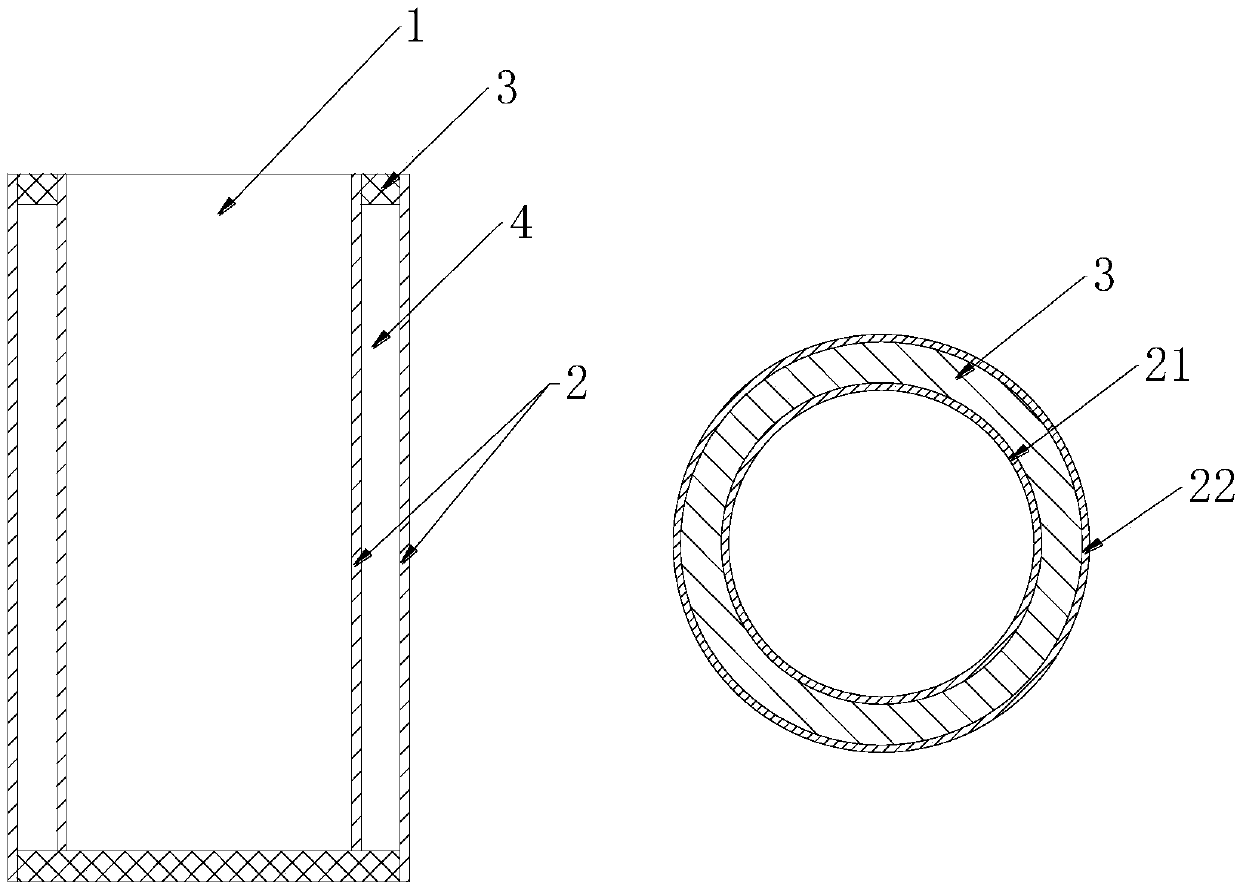
[0052] The heat insulator 2 is made of two circular tube members with different diameters and an open inner cavity, which are divided into a small circular tube 21 and a large circular tube 22. The small circular tube 21 is clamped by a jig Connected in the inner cavity of the large round tube 22, use a jig to clamp and fix one end of the small round tube 21 and the large round tube 22, and make the outer surface of the small round tube 21 and the inner side of the large round tube 22 be separated by the same distance to form a circle. Shape compartment 4 as a vacuum area. The inner cavity of the small round tube 21 is a heating area 1, and the heating area 1 is a tubular cavity with two ends open to accommodate high temperature heating ...
Embodiment 3
[0056] The material and production process of the vacuum insulation equipment described in Example 3 are the same as those in Example 2. The difference lies in that Example 3 further explains another structure of the heat insulator.
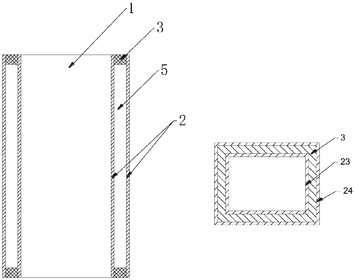
[0057] Such as figure 2 As mentioned above, the heat insulator 2 is made of two different sizes of four-sided square tubes formed by bending with heat insulating material, and is divided into a small square tube 23 and a large square tube 24, and one end of the small square tube 23 is made of a The clamping tool is sleeved in the inner cavity of the large square tube 24, and the distance between the four outer surfaces of the small square tube 23 and the four inner surfaces of the large square tube 24 is the same to form a square compartment 5, and the large square tube 24 is also Clamping is fixed on the jig. An edge-banding material 3 is placed at the port of the compartment where the compartment and the fixture are not in contact with each o...
PUM
| Property | Measurement | Unit |
|---|---|---|
| melting point | aaaaa | aaaaa |
Abstract
Description
Claims
Application Information
 - Generate Ideas
- Intellectual Property
- Life Sciences
- Materials
- Tech Scout
- Unparalleled Data Quality
- Higher Quality Content
- 60% Fewer Hallucinations
Browse by: Latest US Patents, China's latest patents, Technical Efficacy Thesaurus, Application Domain, Technology Topic, Popular Technical Reports.
© 2025 PatSnap. All rights reserved.Legal|Privacy policy|Modern Slavery Act Transparency Statement|Sitemap|About US| Contact US: help@patsnap.com


