
A device for optical fiber side coating

A technology of side coating and optical fiber, which is applied in the field of coating devices, can solve the problems of difficult uniform distribution, time-consuming, uneven coating thickness, etc., and achieve the effect of low requirements for external conditions, simple mechanical structure, and expansion possibility

Active Publication Date: 2020-09-29
BEIHANG UNIV
View PDF6 Cites 0 Cited by
  • Summary
  • Abstract
  • Description
  • Claims
  • Application Information

AI Technical Summary

Problems solved by technology

However, whether it is thermal evaporation or magnetron sputtering, the coating process can only coat the plane perpendicular to the target source more uniformly, and it is obviously not suitable for plane coating of cylinders such as optical fibers.
In the common coating device in the past, in order to realize the coating process of the circular arc surface of the cylinder such as the optical fiber, the commonly used method is to flip the sample to be coated multiple times to coat the coating multiple times to obtain the coated optical fiber, but this method not only obtains different optical fibers. The coating thickness at the position is very uneven and presents an obvious step-like distribution, and because thermal evaporation or magnetron sputtering takes a lot of time to vacuumize, this method takes a lot of time, so there are gradually various ways of rotation Coating method
[0004] At present, the more common optical fiber type cylindrical rotary coating method is double-surface coating, that is, two coatings are completed under the same conditions, and the film is turned 180° for the second coating after the first coating is completed. This makes the optical fiber cylinder There is unevenness in the coating on the body surface
Another way is to fix the optical fiber on a rotatable fixture, and the rotation caused by the external force helps the optical fiber to rotate uniformly to achieve coating. However, this coating method generally only has the rotation of the optical fiber, which is difficult to achieve in the case of multiple target sources. Uniform distribution of components on the fiber surface
Existing technologies are difficult to meet the requirements of uniform and efficient coating on the surface of optical fibers

Method used


Image

  • A device for optical fiber side coating
  • A device for optical fiber side coating
  • A device for optical fiber side coating

Examples


Embodiment

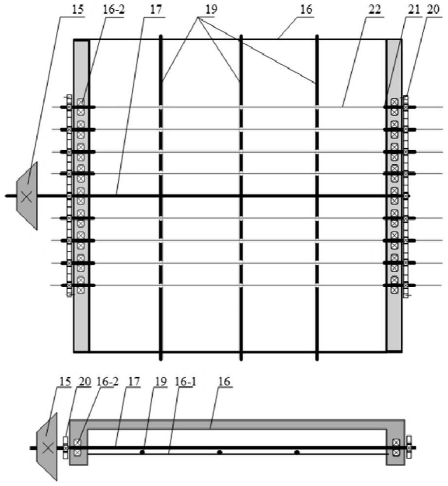
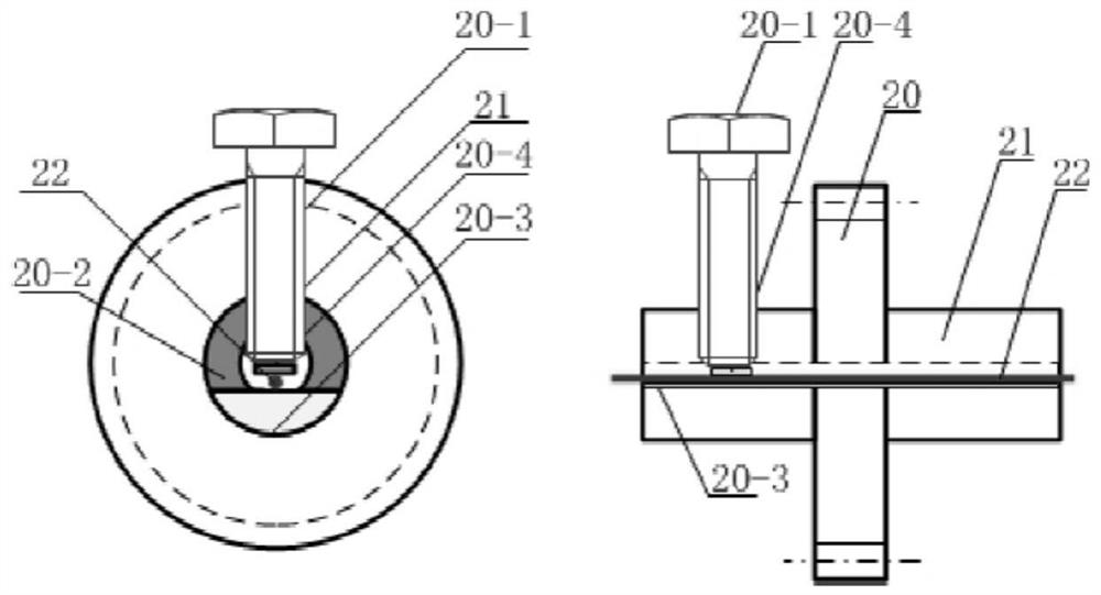
[0030] figure 2 A schematic diagram of the optical fiber clamping device provided by the present invention is given, including: a rotating support steel shaft 17, a power transmission bevel tooth 15, a clamping frame 16, a detachable grooved support rod 19, an optical fiber clamping gear 20, and an optical fiber 22 to be coated; The frame 16 includes a clamp frame side support bar 16-1 and a clamp built-in bearing 16-2, wherein the optical fiber 22 to be coated passes through the image 3 The shown optical fiber clamp gear is fixed with a hollow shaft 21 and supporting screws. There are two ways to fix the optical fiber 22 to be coated and the optical fiber clamp system. One way is to fix both ends of the optical fiber with the optical fiber clamp gear 20. By rotating the supporting steel shaft 17, the gears at both ends rotate at the same angular velocity. In this way, the optical fiber is fixed. The coating can maximize the length of the coating; another way is to fix the ...


PUM


Abstract

The invention discloses a device used for coating the side faces of optical fibers with films. The device comprises a main power shaft, a main power gear, a revolution shaft, a revolution round gear,an internal bearing, a fixed gear, fixed rods of the fixed gear, an autorotation transmission gear, an autorotation power transmitting shaft, an autorotation transmitting bevel gear, a power transmitting bevel gear, a rotating supporting steel shaft, a clamp framework, detachable groove supporting rods loaded on the framework, optical fiber clamp gears and gear internal hollow shafts. According tothe device, after a power device provides rotating force for the main power shaft, the main power shaft transmits rotation to the revolution shaft, and the revolution shaft drives system other partsconnected with the revolution shaft to carry out system revolution around the revolution shaft with the same angle speed; and in the revolution process, the autorotation transmission gear engaged withthe fixed gear can achieve autorotation when doing revolution, the optical fibers can be driven to do autorotation after autorotation is transmitted to the rotating supporting steel shaft through anautorotation transmitting system, and uniform film coating is carried out in the film coating environment. Multiple optical fibers can be synchronously and uniformly coated with films at a time.

Description

technical field [0001] The invention belongs to the technical field of coating devices, in particular to a device for coating the sides of optical fibers, which is a device capable of uniformly coating the arc sides of multiple optical fibers at one time. Background technique [0002] With its unique advantages such as light weight, small size, and anti-electromagnetic interference, optical fibers have been used in more and more fields, especially in the field of sensing. Using the light-transmitting and photosensitive properties of optical fibers, the measurement of physical quantities such as displacement, velocity, acceleration, rotation angle, pressure, temperature, liquid level, current, voltage, and magnetic field can be realized; it can also be applied to the detection of chemical quantities such as gas concentration, It can also be used in the fields of biology and medicine, but in these fields, the optical fiber is only used as the transmission medium of the optical...

Claims


Application Information

Patent Timeline
Patent Type & Authority Patents(China)
IPC IPC(8): C23C14/50
CPCC23C14/505
Inventor 杨远洪宋叔淇李慧
Owner BEIHANG UNIV
Learn More