
Polarization-used fixture, piezoelectric layer polarization method and ultrasonic biometric device manufacturing method

A piezoelectric layer and fixture technology, applied in the field of ultrasonic identification, can solve the problems of incapable of piezoelectric layer polarization, affecting piezoelectric performance of piezoelectric layer, increasing the difficulty of piezoelectric layer polarization, etc., achieving simple operation, preventing The effect of high voltage electrical breakdown

Active Publication Date: 2019-03-19
NANCHANG OUFEI BIOLOGICAL IDENTIFICATION TECH
View PDF6 Cites 3 Cited by
  • Summary
  • Abstract
  • Description
  • Claims
  • Application Information

AI Technical Summary

Problems solved by technology

[0003] Usually in the manufacturing process of the ultrasonic fingerprint recognition device, it is necessary to polarize the piezoelectric layer to make the electric domains of the piezoelectric layer consistent to obtain the maximum piezoelectric performance, and the usual steps are to first coat the piezoelectric material On the thin film transistor with the circuit layer formed, the piezoelectric layer is then polarized. Due to the existence of an exposed circuit layer (such as an ITO layer) on the thin film transistor, the exposed circuit layer is easily exposed to high voltage. If the piezoelectric layer is broken down, the polarization of the piezoelectric layer is more difficult, and with the current polarization method, if there are defects or breakdown points in the piezoelectric layer, the piezoelectric layer cannot be effectively polarized, thereby affecting the piezoelectric layer. Piezoelectric properties of layers

Method used


Image

  • Polarization-used fixture, piezoelectric layer polarization method and ultrasonic biometric device manufacturing method
  • Polarization-used fixture, piezoelectric layer polarization method and ultrasonic biometric device manufacturing method
  • Polarization-used fixture, piezoelectric layer polarization method and ultrasonic biometric device manufacturing method

Examples


preparation example Construction

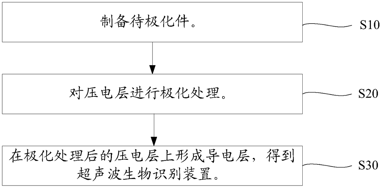
[0046] like figure 1 As shown, the preparation method of an ultrasonic biometric identification device in one embodiment includes the following steps:

[0047] Step S10: Prepare the member to be polarized.

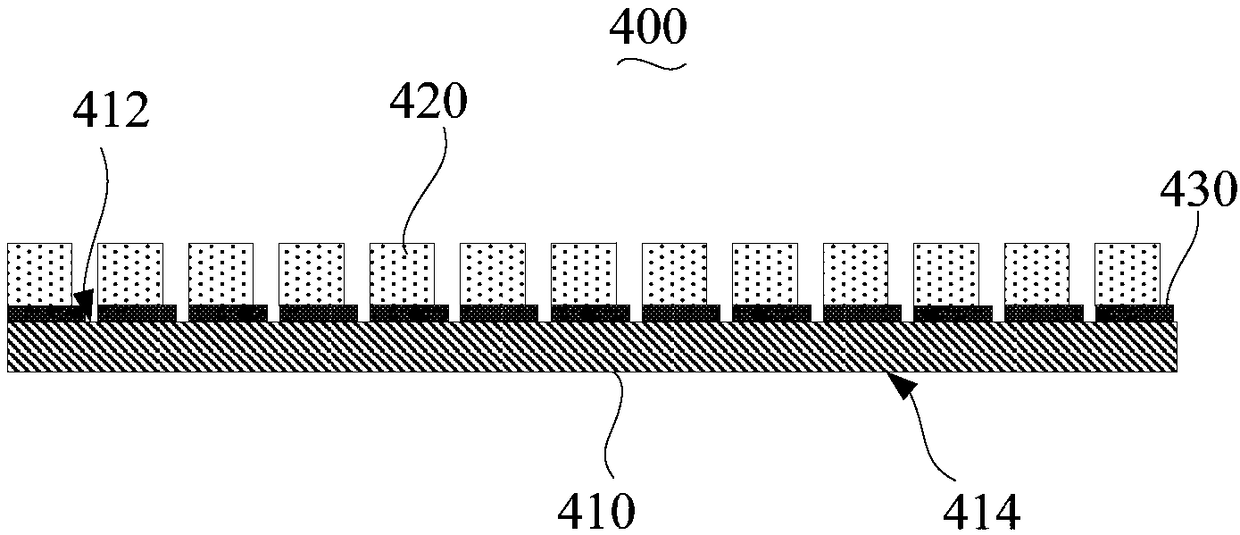
[0048] Please also refer to figure 2 , the member 400 to be polarized includes a substrate 410 and a piezoelectric layer 420, the substrate 410 has an opposite first surface 412 and a second surface 414, the first surface 412 is provided with a circuit layer 430, and the piezoelectric layer 420 is stacked on the first surface 412 and cover part of the circuit layer 430 . In the illustrated embodiment, multiple columns of piezoelectric layers 420 are formed on the first surface 412 of the substrate 410 , and the multiple columns of piezoelectric layers 420 are parallel. Wherein, each column of piezoelectric layers 420 has a plurality of piezoelectric layers 420 at intervals.

[0049] Specifically, the substrate 410 is a thin film transistor. The material of the piezoe...

Embodiment 1

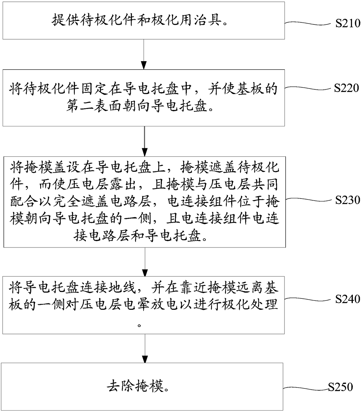
[0096] The piezoelectric layer polarization method of the above step S20 is used to simultaneously polarize the piezoelectric layers 420 of the plurality of components to be polarized 400, wherein the material of the piezoelectric layer 420 is a copolymer of polyvinylidene fluoride and trifluoroethylene The molar ratio of polyvinylidene fluoride and trifluoroethylene is 60:40, the working area of ​​the plate-shaped body 532 of the mask 530 and the thickness of each masking part 534 are 0.7 mm, and the polarization equipment used for polarization is The corona polarization equipment of American Areesys Technology Company, the voltage of the metal grid is -2kV; the voltage of the corona roller is -6.5kV.


PUM


Abstract

The invention relates to a polarization-used fixture, a piezoelectric layer polarization method and an ultrasonic biometric device manufacturing method. The polarization-used fixture is used for beingmounted on a to-be-polarized piece, and comprises a conductive tray, a mask and an electrical connection assembly, wherein the conductive tray is used for mounting the to-be-polarized piece and can be connected with a ground wire; the mask can be arranged on the conductive tray in a covering mode and can cover the to-be-polarized piece in the conductive tray to enable the piezoelectric layer to be exposed, the mask can be cooperated with the piezoelectric layer to completely cover a circuit layer, and the mask is made of polyetherimide plastic; the electrical connection assembly is mounted onthe mask and can be electrically connected with the circuit layer and the conductive tray, and when the mask is arranged on the conductive tray in a covering mode, the electrical connection assemblyis located at the side, facing the conductive tray, of the mask. By using the polarization-used fixture, the piezoelectric layer polarization method is simple to operate, and the piezoelectric layer on a thin film transistor can realize effective polarization.

Description

technical field [0001] The invention relates to the technical field of ultrasonic identification, in particular to a jig for polarization, a method for polarizing a piezoelectric layer, and a method for preparing an ultrasonic biometric identification device. Background technique [0002] Ultrasonic fingerprint recognition technology can scan fingerprints through ultrasonic waves. Compared with traditional fingerprint recognition methods, ultrasonic fingerprint recognition can analyze fingerprints more deeply. Even if there is dirt on the surface of the finger, it will not hinder ultrasonic sampling, and can even penetrate The unique 3D features of fingerprints are identified beneath the surface of the skin. Even when there is water or sweat on the hands, it can still be accurately identified. [0003] Usually, in the manufacturing process of ultrasonic fingerprint identification device, it is necessary to polarize the piezoelectric layer to make the electric domains of the...

Claims


Application Information

Patent Timeline
Patent Type & Authority Applications(China)
IPC IPC(8): H01L41/257G06K9/00H10N30/045
CPCG06V40/1306H10N30/045
Inventor 汪羽
Owner NANCHANG OUFEI BIOLOGICAL IDENTIFICATION TECH
Learn More